
Repair Chevrolet Repair Toyota Repair Honda Repair AvtoVAZ Repair Mercedes-Benz Repair BMW Repair Opel
Home  |  Contacts  |  Sitemap  |    
English Русский
Български
Беларускі
Український
Српски
Hrvatski
Română
Polski
Slovenský
Magyar
AudiManual.ru


  • AUDI 80
  • AUDI 100
  • AUDI A3
  • AUDI A4
  • AUDI A6
  • AUDI A8
  • AUDI Q
  • OTHER
  • ARTICLES
C5 Allroad (1999-2005) C5 (1997-2004) C4 (1994-1997)

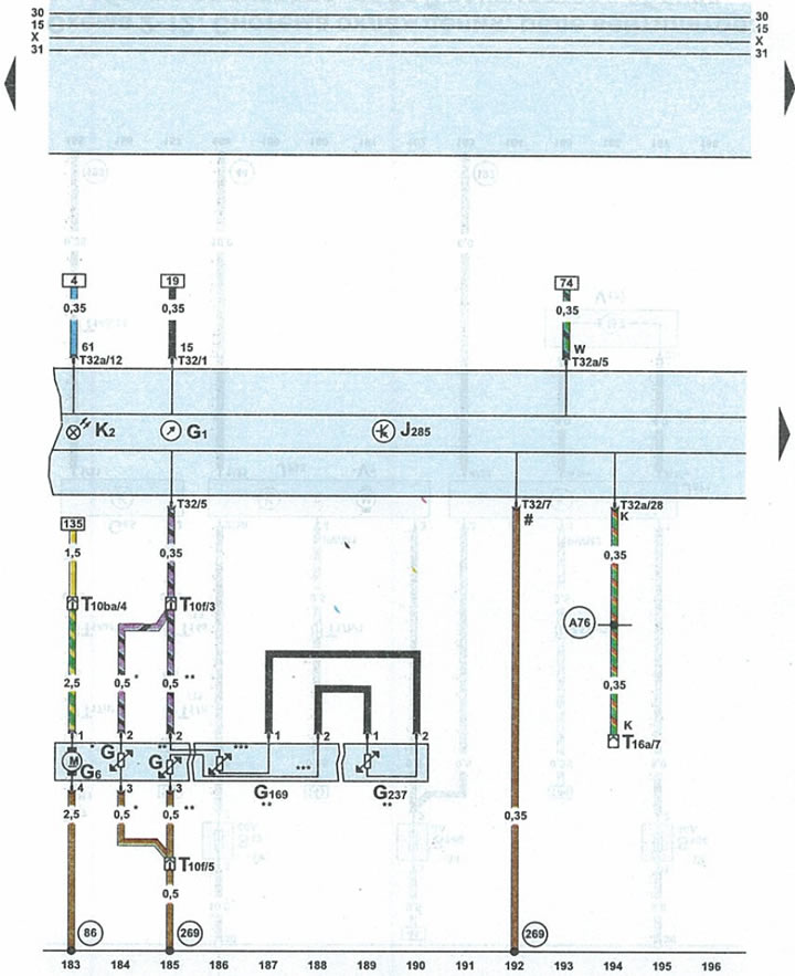
Diagram 2-14. Instrument cluster, fuel pump, fuel gauge (Audi A6 C5)
  • Home
  • Audi A6
  • C5 Allroad (1999-2005)
  • Electrical equipment
  • Schemes (petrol engine 4.2 l)
  • Diagram 2-14. Instrument cluster, fuel pump, fuel gauge
            0

Diagram 2-14. Instrument cluster, fuel pump, fuel gauge


Diagram 2-14. Instrument cluster, fuel pump, fuel gauge


Gfuel gauge sensor
G1fuel gauge
G6fuel pump
G169fuel gauge sensor 2
G237fuel gauge sensor 3
J285instrument cluster microprocessor
K2battery charging indicator light
T10f10-pin brown plug on the left side of the front pillar
T10ba10-pin blue plug on the left side of the A-pillar
T16a16-pin diagnostic connector plug
T3232-pin blue plug on the instrument panel
T32a32-pin green plug on the instrument panel
86wire 1 "ground" (-) in the wiring harness of the rear part of the engine compartment
269connection of 1 sensor to "ground" in the instrument panel wiring harness
A76wire to diagnostic connector in instrument cluster wiring harness
*front wheel drive vehicles
**4WD vehicles wire in fuel tank
#sensor contact with "ground" (-)


The original version is on the portal AUDIMANUAL.RU
The article was checked by auto expert Alexey Ivanov
This article is available at russian, bulgarian, belarusian, ukrainian, serbian, croatian, romanian, polish, slovak, hungarian

Share information:
Previous articles
Audi A6 C5 Allroad: Schemes (petrol engine 4.2 l)
Next articles

Scheme 2.13. Cooling system, radiator fan relay, coolant pump…
Diagram 2-12. Cooling system, radiator fan relay...
Scheme 2.11. Engine control unit, CAN-Bus data exchange bus...
Scheme 2-10. Engine control unit, fuel pump relay, main lambda…
Scheme 2-15. Instrument panel


Similar articles on other Audi car models:
Electrical connection diagram of the fuel system and fuel pump… Audi 80 B3 (1986-1991, petrol)
Instrument cluster, fuel gauge, coolant temperature gauge... Audi 100 C4 (1990-1994, petrol)
Instrument cluster unit, combi-processor in the instrument… Audi A3 Type 8L (1996-2003)
Fuel level sensor; Fuel lift pump; Instrument cluster control… Audi A4 B8 (2007-2015)
Fuel pump / fuel level sensor Audi A8 D2 (1994-2002)
Instrument cluster control unit, ashtray and cup holder… Audi Q7 Typ 4L (2005-2015, diesel)
Fuel level indicator sensor wiring diagram Audi A2 (1999-2005)
Link to this page in different formats


Visitor comments

No comments yet


How much will 17 + 14 =


A6(C5 AR, 1999-2005) 
  • General information
  • User manual
  • Maintenance
  • Troubleshooting
  • Power unit
  • V6 petrol engines
  • V8 petrol engines
  • Diesel engines
  • Cooling and heating system
  • Injection system (gasoline)
  • Fuel system (diesel)
  • Supply system
  • Exhaust system
  • Ignition system
  • Transmission
  • Clutch
  • Mechanical gearbox
  • Automatic gearbox
  • Chassis
  • Brake system
  • Car suspension
  • Steering
  • Body
  • Body elements
  • Doors, locks and windows
  • Electrical equipment
  • Equipment and devices
  • Power devices
  • Electrical circuits
  • Schemes (petrol engine 2.7 l)
  • Schemes (petrol engine 4.2 l)
  • Schemes (diesel engine 2.5 l)
 
A6(C5, 1997-2004) 
  • General information
  • User manual
  • Maintenance
  • Power unit
  • Engine repair
  • Cooling system
  • Fuel system
  • Engine management
  • Fuel system (diesel)
  • Exhaust system
  • Transmission
  • Clutch
  • Car gearbox
  • Chassis
  • Front suspension
  • Rear suspension
  • Steering
  • Wheels and tires
  • Brake system
  • Body
  • Exterior
  • Interior
  • Electrical equipment
  • Air conditioner
  • Equipment and devices
  • Electrical circuits
 
A6(C4, 1994-1997) 
  • General information
  • User manual
  • Maintenance (gasoline)
  • Maintenance (Diesel)
  • Gasoline engines
  • 4 cylinder engines
  • 5 cylinder engines
  • 6 cylinder engines
  • Diesel engines
  • 4 cylinder engines
  • 5 cylinder engines
  • Engine repair
  • Removal and reassembly
  • Cooling system
  • Single point injection system
  • Multipoint injection system
  • MPI/MPFI injection system
  • Fuel system (diesel)
  • Exhaust system
  • Ignition system
  • Transmission
  • Clutch
  • Manual transmission
  • Automatic transmission
  • Drive shafts
  • Chassis
  • Brake system
  • Front suspension
  • Rear suspension
  • Steering
  • Body
  • Exterior (external elements)
  • Interior (internal elements)
  • Electrical equipment
  • Power devices
  • Lighting and appliances
  • Electrical circuits
 
AudiManual.ru © 2017-2026 · Mobile version · Feedback · Sitemap: EN BG BY UA RS HR RO PL SK HU · Site search · News and articles
80 B2 · 80 B3 petrol · 80 B3 · 80 B4 · 100 C3 diesel · 100 C3 petrol · 100 C3 · 100 C4 petrol · 100 C4 · A3 Type 8L · A4 B5 petrol · A4 B5 · A4 B6 petrol · A4 B6 · A4 B7 · A4 B8 · A6 C4 · A6 C5 · A6 C5 Allroad · A8 D2 · Q5 Type 8R · Q7 Typ 4L · Audi A2 ·
This site uses cookies 🍪. Click the button to accept this fact.