



Fuel level sensor; Fuel booster pump; Instrument cluster control unit
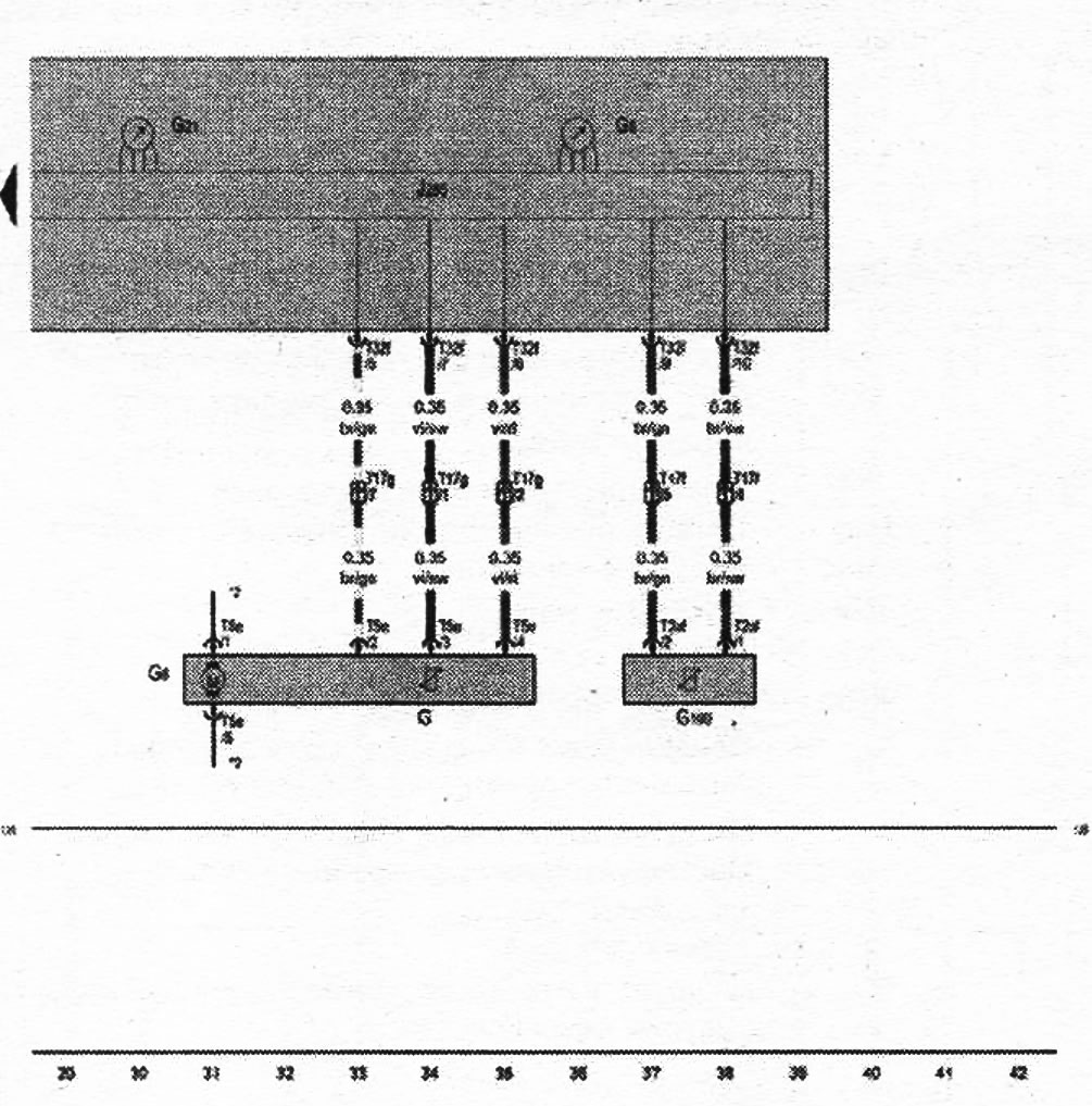
| G | Fuel level sensor |
| G5 | Tachometer |
| G6 | Fuel booster pump |
| G21 | Speedometer |
| G169 | Fuel level sensor 2 |
| J285 | Instrument cluster control unit |
| T2af | Connector, 2-pin |
| T5e | 5-pin connector |
| T17f | Connector, 17-pin, in the junction box of the right A-pillar |
| T17g | Connector, 17-pin, in the junction box of the right A-pillar |
| T32f | Connector, 32-pin |
| 135 | Ground 2 connection in instrument cluster and control harness |
* - depending on the configuration.
*2 - see the current electrical circuit diagram for the engine.
- ws = white
- sw = black
- ro = red
- rt = red
- br = brown
- gn = green
- bl = blue
- gr = gray
- li = purple
- vi = purple
- ge = yellow
- or = orange
- rs = pink
(The original publication in its entirety is posted on the website «audimanual.ru»)