
Scheme 2-10. Engine control unit, fuel pump relay, main lambda probes
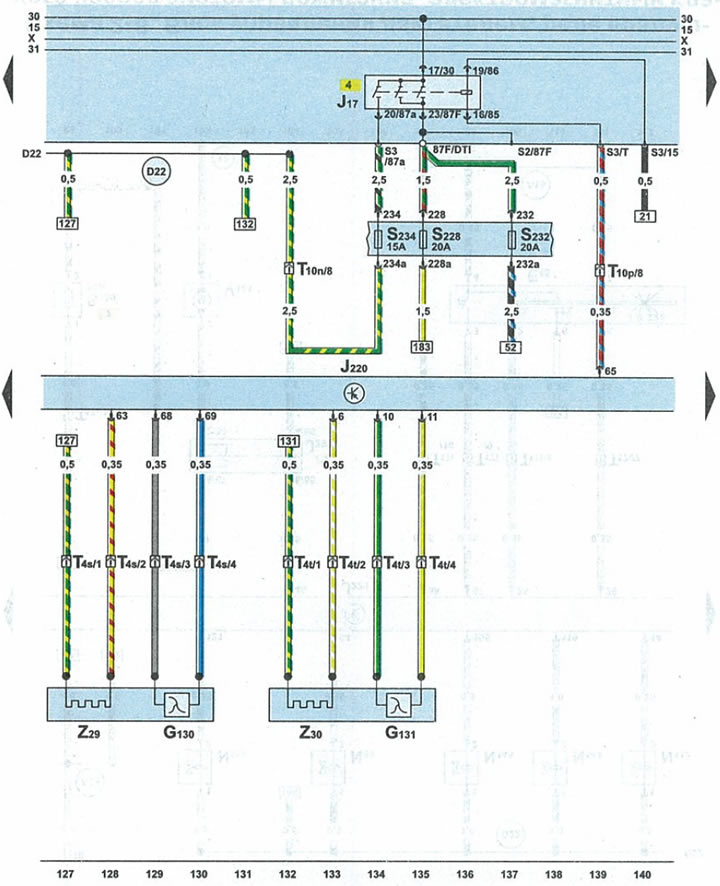
| G130 | main lambda probe 1 (after catalyst) |
| G131 | main lambda probe 2 (after catalyst) |
| J17 | fuel pump relay |
| J220 | engine control unit |
| S228 | fuse 28 |
| S232 | fuse 32 |
| S234 | fuse 34 |
| T4s | 4-pin green plug main lambda probe 1 |
| T4t | 4-pin brown plug main lambda probe 2 |
| T10n | 10-pin orange connector on the fuse/relay box under the fairing |
| T10p | 10-pin black connector on fuse/relay box under fairing |
| Z29 | main lambda probe heater 1 |
| Z30 | main lambda probe heater 2 |
| D22 | connecting the wires through fuse 34 in the wiring harness on the right side of the engine compartment |