Repair Chevrolet Repair Toyota Repair Honda Repair AvtoVAZ Repair Mercedes-Benz Repair BMW Repair Opel
Home  |  Contacts  |  Sitemap  |    
English Русский
Български
Беларускі
Український
Српски
Hrvatski
Română
Polski
Slovenský
Magyar
AudiManual.ru


  • AUDI 80
  • AUDI 100
  • AUDI A3
  • AUDI A4
  • AUDI A6
  • AUDI A8
  • AUDI Q
  • OTHER
  • ARTICLES
C5 Allroad (1999-2005) C5 (1997-2004) C4 (1994-1997)

Scheme 2-8. Engine control unit, air pump relay of the afterburning system... (Audi A6 C5)

  • Home
  • Audi A6
  • C5 Allroad (1999-2005)
  • Electrical equipment
  • Schemes (petrol engine 4.2 l)
  • Scheme 2-8. Engine control unit, air pump relay of the afterburning system...
            0

Scheme 2-8. Engine control unit, air pump relay of the afterburning system, electromagnetic valve 1 of the adsorber purge, cruise control switch
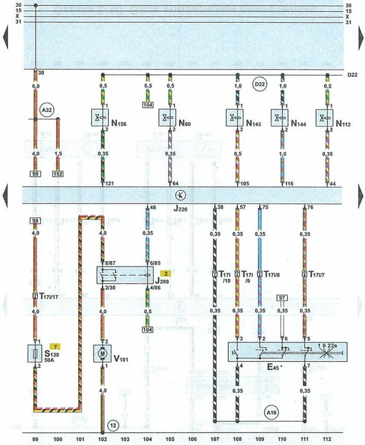


Scheme 2-8. Engine control unit, air pump relay of the afterburning system, electromagnetic valve 1…


E45cruise control switch
J220engine control unit
J299air pump relay of the afterburning system
N80evaporative Canister Purge Solenoid Valve 1
N112afterburner valve (supplying air to the exhaust valves)
N144left hydraulic engine mount solenoid valve
N145electromagnetic valve of the right hydraulic support of the engine mount
N156intake throttle actuator valve
S130fuse for air pump of afterburning system.
T17i17-pin white plug for under cowl fuse/relay box
V101afterburner pump electric motor
12ground point (-) in the engine compartment on the left
A16cruise control wire in instrument cluster wiring harness
A32positive potential wire terminal 30 in the instrument panel wiring harness
D22connection on the circuit protected by fuse 34 in the engine compartment wiring harness on the right
*cars with cruise control
The article was checked by auto expert Alexey Ivanov
This article is available at russian, bulgarian, belarusian, ukrainian, serbian, croatian, romanian, polish, slovak, hungarian

Share information:
Previous articles
Audi A6 C5 Allroad: Schemes (petrol engine 4.2 l)
Next articles

Scheme 2-7. Engine control unit, inductive sensors (Hall…
Diagram 2-6. Engine control unit, knock sensor...
Diagram 2-5. Engine control unit, throttle valve, accelerator…
Diagram 2-4. Engine control unit, fuel injectors and ignition…
Scheme 2-9. Engine control unit, preliminary lambda probes...
Scheme 2-10. Engine control unit, fuel pump relay, main lambda…
Scheme 2.11. Engine control unit, CAN-Bus data exchange bus...
Diagram 2-12. Cooling system, radiator fan relay...


Similar articles on other Audi car models:
Electrical diagram of the fuel pump, fuel injection system,… Audi 80 B4 (1991-1996)
Mono-Motronic injection system control unit, fuel pump relay,… Audi 100 C4 (1990-1994, petrol)
Control unit for Simos, fuel pump relay, injectors, ignition… Audi A3 Type 8L (1996-2003)
Functioning of the control and injection system of a gasoline… Audi A4 B6 (2000-2006)
Oil pan and oil pump for 2.5L diesel engine Audi A8 D2 (1994-2002)
Comfort system control unit, heated rear window and its relay,… Audi Q7 Typ 4L (2005-2015, diesel)
Removal and installation the central control unit of the comfort… Audi A2 (1999-2005)
Link to this page in different formats


Visitor comments

No comments yet


How much will 41 + 48 =


A6(C5 AR, 1999-2005) 
  • General information
  • User manual
  • Maintenance
  • Troubleshooting
  • Power unit
  • V6 petrol engines
  • V8 petrol engines
  • Diesel engines
  • Cooling and heating system
  • Injection system (gasoline)
  • Fuel system (diesel)
  • Supply system
  • Exhaust system
  • Ignition system
  • Transmission
  • Clutch
  • Mechanical gearbox
  • Automatic gearbox
  • Chassis
  • Brake system
  • Car suspension
  • Steering
  • Body
  • Body elements
  • Doors, locks and windows
  • Electrical equipment
  • Equipment and devices
  • Power devices
  • Electrical circuits
  • Schemes (petrol engine 2.7 l)
  • Schemes (petrol engine 4.2 l)
  • Schemes (diesel engine 2.5 l)
 
A6(C5, 1997-2004) 
  • General information
  • User manual
  • Maintenance
  • Power unit
  • Engine repair
  • Cooling system
  • Fuel system
  • Engine management
  • Fuel system (diesel)
  • Exhaust system
  • Transmission
  • Clutch
  • Car gearbox
  • Chassis
  • Front suspension
  • Rear suspension
  • Steering
  • Wheels and tires
  • Brake system
  • Body
  • Exterior
  • Interior
  • Electrical equipment
  • Air conditioner
  • Equipment and devices
  • Electrical circuits
 
A6(C4, 1994-1997) 
  • General information
  • User manual
  • Maintenance (gasoline)
  • Maintenance (Diesel)
  • Gasoline engines
  • 4 cylinder engines
  • 5 cylinder engines
  • 6 cylinder engines
  • Diesel engines
  • 4 cylinder engines
  • 5 cylinder engines
  • Engine repair
  • Removal and reassembly
  • Cooling system
  • Single point injection system
  • Multipoint injection system
  • MPI/MPFI injection system
  • Fuel system (diesel)
  • Exhaust system
  • Ignition system
  • Transmission
  • Clutch
  • Manual transmission
  • Automatic transmission
  • Drive shafts
  • Chassis
  • Brake system
  • Front suspension
  • Rear suspension
  • Steering
  • Body
  • Exterior (external elements)
  • Interior (internal elements)
  • Electrical equipment
  • Power devices
  • Lighting and appliances
  • Electrical circuits
 
AudiManual.ru © 2017-2026 · Mobile version · Feedback · Sitemap: EN BG BY UA RS HR RO PL SK HU · Site search · News and articles
80 B2 · 80 B3 petrol · 80 B3 · 80 B4 · 100 C3 diesel · 100 C3 petrol · 100 C3 · 100 C4 petrol · 100 C4 · A3 Type 8L · A4 B5 petrol · A4 B5 · A4 B6 petrol · A4 B6 · A4 B7 · A4 B8 · A6 C4 · A6 C5 · A6 C5 Allroad · A8 D2 · Q5 Type 8R · Q7 Typ 4L · Audi A2 ·
This site uses cookies 🍪. Click the button to accept this fact.