
Table of contents: Motronic control system components… ↓ Fuel rail and injectors. Engine 1.8L… ↓ Control system elements in the V6… ↓ Control system components in the… ↓ Sensors and actuators of the… ↓ Switchable intake manifold (2.0L ALT… ↓ Accelerator servo ↓
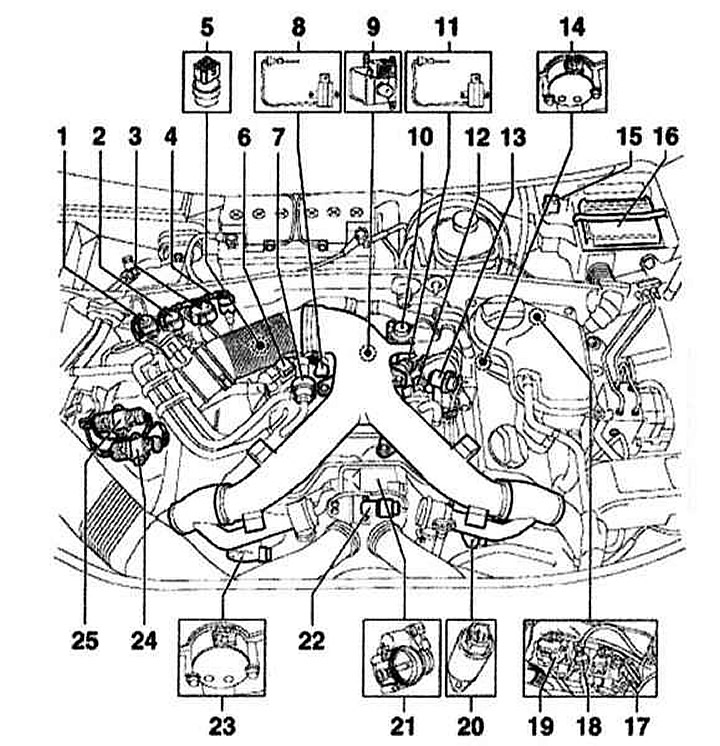
Motronic control system components in the 1.8L engine bay (AVJ, BFB)
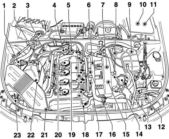
- 1 — Electromagnetic valve 1 to control the adsorber
- 2 — Pre-catalytic converter lambda probe, 55Nm
- 3 — Lambda probe of additional catalytic converter, 55Nm
- 4 — Secondary air inlet combination valve
- 5 — Coolant temperature sensor
- 6 — Engine speed sensor
- 7 — Secondary air inlet valve
- 8 — Connector holder under the coolant expansion tank. To disconnect the connector, disconnect the expansion tank and tilt it to the side
- 9 — Connector holder. Disconnect the connector, pos. 8
- 10 — Water collection compartment (electronics box). Installation location of the engine control unit with integrated height sensor, as well as for the injection system current relay.
- 11 — Water collection compartment (electronics box) with secondary air mixing pump relay
- 12 — Boost pressure sensor. At the top of the intercooler
- 13 — Throttle control unit
- 14 — Intake air temperature sensor
- 15 — Turbocharger circulation valve. Located under the intake manifold
- 16 — Knock sensor 1
- 17 — Knock sensor 2
- 18 — Hall sensor
- 19 — Injector
- 20 — Ignition coil
- 21 — Boost limitation solenoid valve
- 22 — Air mass meter
- 23 — Secondary air pump electric motor
Fuel rail and injectors. Engine 1.8L AVJ/BFB
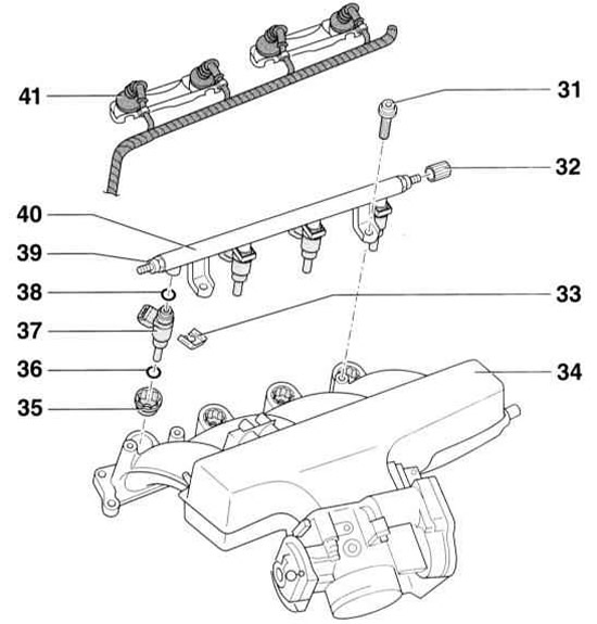
- 31 - Screw, 10Nm
- 32 — Protective cover
- 33 — Retaining clip. Ensure correct position on injector and fuel rail
- 34 — Intake manifold with throttle control unit and intake air temperature sensor
- 35 — Injector insert, 3Nm. Screwed in with thread locking agent D000600A2
- 36 — O-ring. Be sure to replace. Lubricate with clean engine oil before installation.
- 37 — Injector
- 38 - O-ring. Be sure to replace. Lubricate with clean engine oil before installation.
- 39 — Fuel supply line, 25Nm
- 40 — Fuel distribution line
- 41 — Connector
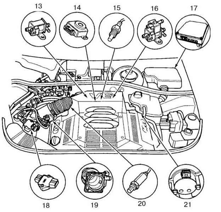
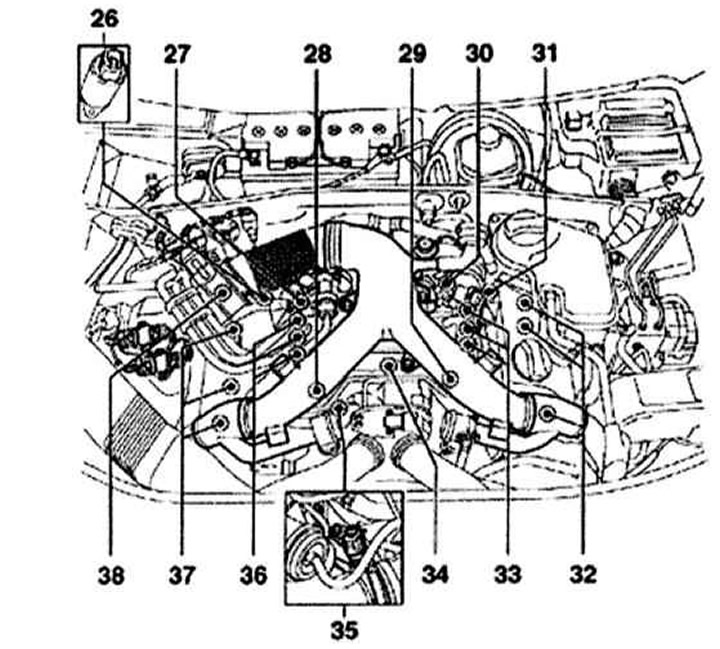
Control system elements in the V6 engine bay
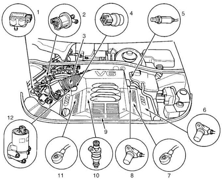
- 1 - EVAP sensor
- 2 - EVAP purge valve
- 3 — Fuel pressure regulator
- 4 — ECT sensor
- 5 - Heated lambda probe
- 6 — CKP sensor
- 7 — Knock sensor 2
- 8 — Crankshaft speed sensor
- 9 — Ignition coils
- 10 — Injector
- 11 — Knock sensor 1
- 12 — IAC valve
- 13 - Intake air duct switching valve
- 14 — TPS
- 15 — EGR temperature sensor
- 16 — EGR vacuum control solenoid valve
- 17 — PCM
- 18 — CMP sensor
- 19 — Heated lambda probe
- 20 — MAF sensor
- 21 — Ignition coil output stage
Control system components in the engine compartment of the S4 model
- 1 — Lambda probe 1 wiring connector behind the catalytic converter
- 2 — Lambda probe 2 wiring connector behind the catalytic converter
- 3 — Heated lambda probe wiring connector in block 1
- 4 — Block 1 knock sensor wiring connector
- 5 — ECT sensor
- 6 — Exhaust gas bypass control valve
- 7 — EVAP purge valve
- 8 — Temperature sensor #1 on the outlet
- 9 — Additional air intake solenoid valve
- 10 — Additional air intake pump electric motor
- 11 — Temperature sensor #2 on the outlet
- 12 — Turbocharger circulation valve
- 13 — Air pressure regulator
- 14 — CMP sensor block 2
- 15 — Additional air intake pump relay
- 16 — ECM
- 17 — Crankshaft speed sensor wiring connector
- 18 — Block 2 knock sensor wiring connector
- 19 — Heated lambda probe wiring connector in block 2
- 20 — Solenoid valve for adjusting the camshaft in block 2
- 21 — Throttle valve control module
- 22 — Compressed air pressure sensor
- 23 — CMP sensor block 1
- 24 — Ignition coil output stage in block 2
- 25 — Ignition coil output stage in block 1
- 26 — Solenoid valve for adjusting the camshaft in block 1
- 27 — Heated lambda probe wiring connector in block 2
- 28 — Knock sensor #1
- 29 — Knock sensor #2
- 30 — VSS sensor, in transmission
- 31 — Heated lambda probe in block 2
- 32 — Ignition coils of block 2
- 33 — Block 2 injectors
- 34 — IAT sensor
- 35 — IAT sensor wiring connector
- 36 — Block 1 injectors
- 37 — Ignition coils of block 1
- 38 — MAF sensor
Fuel is drawn from the fuel tank by an electric fuel pump and supplied through a fuel filter to the fuel rail. The pressure regulator maintains the pressure in the fuel system equal to 3.5, 4.0 or 6.0 atm., depending on the engine.
The fuel is injected pulsed into the intake manifold, located directly in front of the engine intake valves, via electrically controlled injectors. The engine control unit sequentially controls the injectors in accordance with the ignition sequence, regulates the injection time and, thus, the amount of fuel injected.
The air needed to form the fuel mixture is sucked into the engine through the air filter and passes through the throttle valve and the intake manifold to the intake valves. The amount of air sucked in is controlled by the throttle valve, which is moved by a stepper motor controlled by the engine control unit. In turbocharged engines, the sucked in air is compressed by a turbocharger driven by the exhaust gases of the exhaust system. The compressed air is then cooled in the charge air cooler and fed to the engine to form the fuel mixture.
The volume of air sucked in is determined by the air volume meter. The meter is located in the air intake duct. The meter housing contains a thin, electrically heated sensor plate, cooled by the flow of sucked air. The electric current that heats the plate is regulated by the control system in such a way as to maintain the temperature of the plate constant. If, for example, the amount of air sucked in increases, the temperature of the heated plate begins to decrease. At the same time, the magnitude of the electric current immediately increases in order to maintain the temperature of the plate unchanged. Fluctuations in the electric current of the plate indicate to the engine control unit its load state, which allows the amount of fuel injected to be correctly determined.
The control unit determines the optimal ignition time, injection moment and the amount of fuel injected. At the same time, the control unit's operation is coordinated with other vehicle systems, such as the gearbox control or anti-theft system.
Information from other sensors and control voltages supplied to the actuators ensure optimal engine operation in any situation. If some sensors fail, the control unit switches to the emergency program mode to prevent possible engine damage and ensure further movement of the vehicle. In this case, the engine runs unevenly and tends to stall when the gas is increased.
Sensors and actuators of the injection system
Crankshaft position sensor screwed into the cylinder block near the flywheel. It transmits information about the engine speed and the TDC position of the first cylinder piston to the control unit.
Camshaft Position Sensor is located at the end of the cylinder head cover. Together with the crankshaft position sensor, it transmits information about the TDC of the piston of the first cylinder to the control unit. It serves to synchronize the ignition timing and ignition sequence.
Throttle potentiometer is located in the actuator of the throttle valve and informs the control unit of the current angle of the throttle valve position. The second potentiometer informs the control unit of the base value and generates a backup signal in the event of failure of the throttle valve potentiometer.
Accelerator pedal sensor is located in the area of the driver's feet directly on the pedal axis. It informs the control unit about the pedal position. For reliability reasons, a duplicate signal is received from the pedal sensor, as well as from the throttle potentiometer.
Coolant temperature sensors is located in the thermostat housing. It is a resistor with a negative temperature coefficient, the resistance of which decreases with increasing temperature.
Intake air temperature sensor also represents an NTC resistor.
The fuel tank ventilation system consists of adsorber and an electromagnetic valve. The adsorber accumulates fuel vapors formed as a result of heating the fuel. When the engine is running, the vapors are sucked out of the adsorber and fed into the combustion chambers of the engine.
Lambda probes (oxygen sensors) measure the oxygen content in the exhaust gases before and after the catalytic converter and transmit the corresponding signals to the engine control unit. One lambda probe is located before and the other after the catalytic converter.
Knock sensor screwed into the side of the cylinder block. It prevents the occurrence of dangerous shock combustion of the fuel mixture. Thanks to this, the ignition moment can be maintained at the detonation limit, which ensures efficient use of the combustion energy of the fuel and thus reduces fuel consumption.
Switchable intake manifold (2.0L ALT engine)
The required power and torque characteristics are achieved by means of a two-stage switchable intake manifold. The manifold is switched from short to long in the speed range of 2,000 – 3,700 rpm. The switch shaft, which separates the individual intake channels by means of elastic sealing rings and sealing strips, opens the intake tract. Switching between torque and power positions is done electro-pneumatically (depending on load, speed and temperature) (refer to the illustrations below).
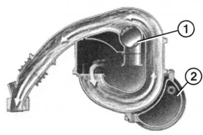
Intake manifold in torque optimisation position
- 1 - Shift roller
- 2 - Vacuum accumulator. On the 2.0L FSI engine, the AWA is located inside the intake manifold
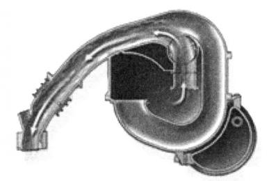
Intake manifold in power optimization position
Accelerator servo
Instead of the usual gas drive, there is a pedal position sensor on the gas pedal (illustration below), which transmits information about the pedal position to the engine control unit. Based on the information received, the control unit controls the position of the throttle valve via the electric motor.
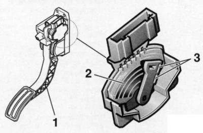
Accelerator pedal sensor
- 1 - Gas pedal
- 2 - Resistive track
- 3 — Sensor 1+2
The position sensor housing contains two contact potentiometers, which are fixed on a common shaft. Each time the pedal position changes, the resistance of the potentiometers and the voltage transmitted to the engine control unit changes.
If any sensor fails, the gas drive malfunction lamp lights up and the fault is registered in the control unit's fault memory. If both sensors fail, the engine runs at an increased speed and no longer responds to the gas pedal.
Throttle actuator unit (refer to the illustration below) includes an electric motor, two potentiometers and a system of gears with a return spring. It regulates the position of the throttle valve. The task of the control unit is to stabilize the idle speed, regardless of the connection of additional consumers, such as the power steering or air conditioning compressor.
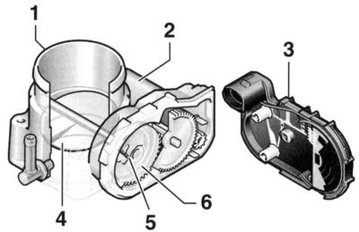
Throttle actuator unit
- 1 — Throttle body
- 2 — Throttle actuator
- 3 - Housing cover with built-in electronics
- 4 — Throttle valve
- 5 — Throttle potentiometer (throttle actuator angle sensor 1+2)
- 6 - Spring return gear
The throttle potentiometer is located at the throttle shaft and transmits current information about the throttle position angle to the control unit. The second potentiometer transmits information about the reference value to the control unit and provides a backup signal if the potentiometer fails.
[This article was copied from an online resource: AUDIMANUAL.ru]