Repair Chevrolet Repair Toyota Repair Honda Repair AvtoVAZ Repair Mercedes-Benz Repair BMW Repair Opel
Home  |  Contacts  |  Sitemap  |    
English Русский
Български
Беларускі
Український
Српски
Hrvatski
Română
Polski
Slovenský
Magyar
AudiManual.ru


  • AUDI 80
  • AUDI 100
  • AUDI A3
  • AUDI A4
  • AUDI A6
  • AUDI A8
  • AUDI Q
  • OTHER
  • ARTICLES
C5 Allroad (1999-2005) C5 (1997-2004) C4 (1994-1997)

Scheme 2-7. Engine control unit, inductive sensors (Hall sensors)... (Audi A6 C5)

  • Home
  • Audi A6
  • C5 Allroad (1999-2005)
  • Electrical equipment
  • Schemes (petrol engine 4.2 l)
  • Scheme 2-7. Engine control unit, inductive sensors (Hall sensors)...
            0

Scheme 2-7. Engine control unit, inductive sensors (hall sensors), brake light switch, brake booster pressure sensor
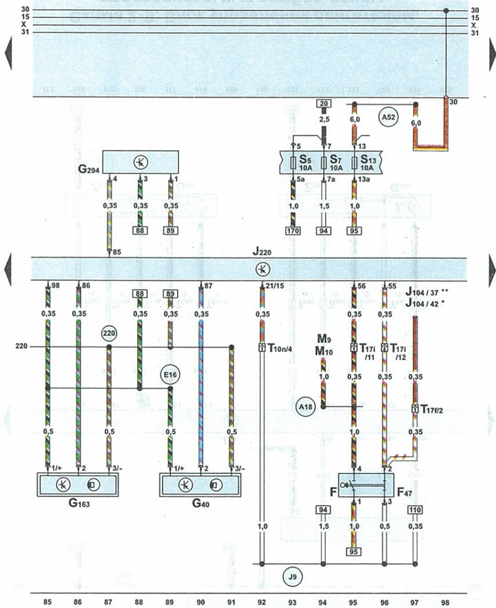


Scheme 2-7. Engine control unit, inductive sensors (hall sensors), brake light switch, brake…


Fbrake light switch
F47cruise control switch sensor
G40camshaft position sensor 1
G163camshaft position sensor 2
G294brake booster pressure sensor
J104ABS control unit with EDS
J220engine control unit
M9brake light bulb in rear left headlight
M10brake light bulb in rear right headlight
S5fuse
S7fuse
S13fuse
T10n10-pin orange connector for under cowl fuse/relay box
T17f17-pin black plug on relay block under small item pocket on driver's side instrument panel
T17i17-pin white plug for under cowl fuse/relay box
220 "mass" (-) (sensor) in the engine wiring harness
A18terminal 54 wire in instrument panel wiring harness
A52wire 2 positive potential terminal 30 in the instrument panel wiring harness
E165V signal transmission wire in the engine control unit wiring harness
J9wire 1 terminal 15a in ABS wiring harness
*cars with ABS series 5.3
**cars with ABS series 5.7
The article was checked by auto expert Alexey Ivanov
This article is available at russian, bulgarian, belarusian, ukrainian, serbian, croatian, romanian, polish, slovak, hungarian

Share information:
Previous articles
Audi A6 C5 Allroad: Schemes (petrol engine 4.2 l)
Next articles

Diagram 2-6. Engine control unit, knock sensor...
Diagram 2-5. Engine control unit, throttle valve, accelerator…
Diagram 2-4. Engine control unit, fuel injectors and ignition…
Diagram 2-3. Engine control unit, fuel injectors and ignition…
Scheme 2-8. Engine control unit, air pump relay of the…
Scheme 2-9. Engine control unit, preliminary lambda probes...
Scheme 2-10. Engine control unit, fuel pump relay, main lambda…
Scheme 2.11. Engine control unit, CAN-Bus data exchange bus...


Similar articles on other Audi car models:
Electrical diagram of the control unit of the fuel system of the… Audi 80 B4 (1991-1996)
Multipoint injection control unit, knock sensors, throttle… Audi 100 C4 (1990-1994, petrol)
Control unit for Motronic, knock sensors, engine speed sensor... Audi A3 Type 8L (1996-2003)
Removal and installation the SRS control unit, sensors and coil… Audi A4 B7 (2004-2008)
E87 Air Conditioning Control Unit Audi A8 D2 (1994-2002)
SRS Components — Removing and Installing the SRS Control Unit… Audi Q7 Typ 4L (2005-2015, diesel)
Engine Control Unit — Check Audi A2 (1999-2005)
Link to this page in different formats


Visitor comments

No comments yet


How much will 28 + 33 =


A6(C5 AR, 1999-2005) 
  • General information
  • User manual
  • Maintenance
  • Troubleshooting
  • Power unit
  • V6 petrol engines
  • V8 petrol engines
  • Diesel engines
  • Cooling and heating system
  • Injection system (gasoline)
  • Fuel system (diesel)
  • Supply system
  • Exhaust system
  • Ignition system
  • Transmission
  • Clutch
  • Mechanical gearbox
  • Automatic gearbox
  • Chassis
  • Brake system
  • Car suspension
  • Steering
  • Body
  • Body elements
  • Doors, locks and windows
  • Electrical equipment
  • Equipment and devices
  • Power devices
  • Electrical circuits
  • Schemes (petrol engine 2.7 l)
  • Schemes (petrol engine 4.2 l)
  • Schemes (diesel engine 2.5 l)
 
A6(C5, 1997-2004) 
  • General information
  • User manual
  • Maintenance
  • Power unit
  • Engine repair
  • Cooling system
  • Fuel system
  • Engine management
  • Fuel system (diesel)
  • Exhaust system
  • Transmission
  • Clutch
  • Car gearbox
  • Chassis
  • Front suspension
  • Rear suspension
  • Steering
  • Wheels and tires
  • Brake system
  • Body
  • Exterior
  • Interior
  • Electrical equipment
  • Air conditioner
  • Equipment and devices
  • Electrical circuits
 
A6(C4, 1994-1997) 
  • General information
  • User manual
  • Maintenance (gasoline)
  • Maintenance (Diesel)
  • Gasoline engines
  • 4 cylinder engines
  • 5 cylinder engines
  • 6 cylinder engines
  • Diesel engines
  • 4 cylinder engines
  • 5 cylinder engines
  • Engine repair
  • Removal and reassembly
  • Cooling system
  • Single point injection system
  • Multipoint injection system
  • MPI/MPFI injection system
  • Fuel system (diesel)
  • Exhaust system
  • Ignition system
  • Transmission
  • Clutch
  • Manual transmission
  • Automatic transmission
  • Drive shafts
  • Chassis
  • Brake system
  • Front suspension
  • Rear suspension
  • Steering
  • Body
  • Exterior (external elements)
  • Interior (internal elements)
  • Electrical equipment
  • Power devices
  • Lighting and appliances
  • Electrical circuits
 
AudiManual.ru © 2017-2026 · Mobile version · Feedback · Sitemap: EN BG BY UA RS HR RO PL SK HU · Site search · News and articles
80 B2 · 80 B3 petrol · 80 B3 · 80 B4 · 100 C3 diesel · 100 C3 petrol · 100 C3 · 100 C4 petrol · 100 C4 · A3 Type 8L · A4 B5 petrol · A4 B5 · A4 B6 petrol · A4 B6 · A4 B7 · A4 B8 · A6 C4 · A6 C5 · A6 C5 Allroad · A8 D2 · Q5 Type 8R · Q7 Typ 4L · Audi A2 ·
This site uses cookies 🍪. Click the button to accept this fact.