
Table of contents: SRS control unit ↓ Shock sensors ↓
Note: Before working on SRS components, be sure to disconnect the battery cables (see chapter 5) and wait at least three minutes after that. After installing the SRS components, first turn on the ignition and then connect the battery.
SRS control unit
1. Disconnect the negative battery cable with the ignition on (see Chapter 5).
2. Remove the storage compartment in the center console and the E380 multimedia control module (see Chapter 10).
3. Give away three nuts (1 in the illustration), remove the SRS 2 control unit from the studs and disconnect its connector (3).
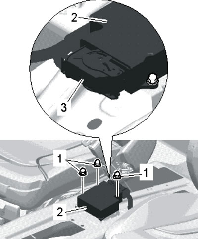
12.3. Removing the SRS control unit.
4. Installation is carried out in reverse order. Tighten the nuts to 9 Nm. If a new SRS unit is installed, it must be programmed.
Shock sensors
5. Frontal impact sensors (2 in the illustration) fastened with two bolts (1) with a force of 9 Nm on the front panel of the body: left and right.
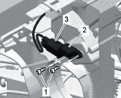
12.5. Removing the front impact sensor.
The sensor can be removed with the hood open.
6. Front side impact sensors (2 in the illustration) fastened with two bolts (1) with a force of 9 Nm on the B-pillar.
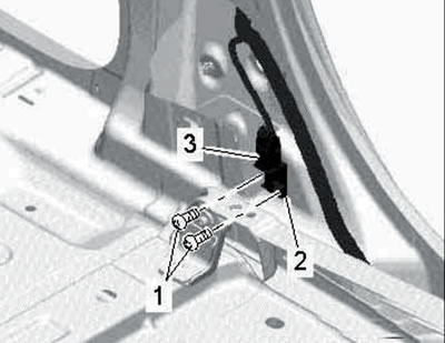
12.6. Removing the front side impact sensor.
The sensor can be removed after removing the lower trim panel of the B-pillar.
7. Rear side impact sensors (2 in the illustration) fastened with two nuts (1) with a force of 9 Nm on the rear C-pillar.
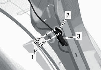
12.7. Removing the rear side impact sensor.
The sensor can be removed after removing the C-pillar trim panel.