
Table of contents: Steering column switch block ↓ Steering column electronic control… ↓ Coil spring and steering wheel angle… ↓ Steering column switches ↓
1. The steering column module consists of a coil spring, a steering angle sensor, steering column paddles and a steering column electronics control unit. The steering column module installation details are shown in the illustration.
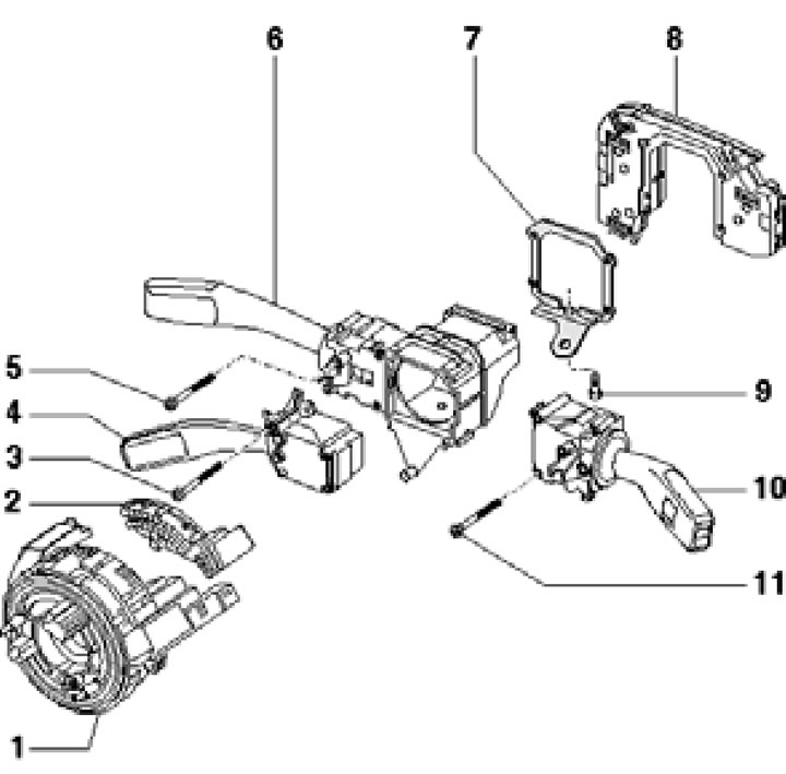
8.1. Steering column module installation details:
1 - Coil spring with sliding ring, do not turn after removing;
2 - Steering wheel angle sensor G85;
3, 5, 11 - Bolt, 0.65 Nm;
4 - Cruise control switch;
6 - Left upper steering column switch;
7 - Holder;
8 - Steering column electronics control unit;
9 - Bolt, 3 Nm;
10 - Right steering column switch.
Steering column switch block
2. Remove the steering wheel (see Chapter 9).
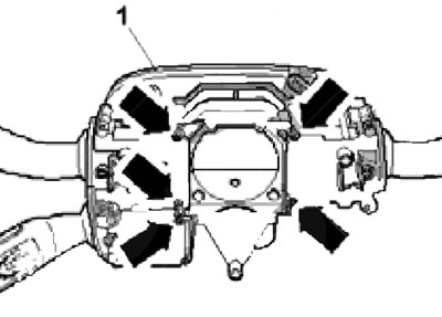
3. Remove the flashing (1 in the illustration) in the direction of the arrow.
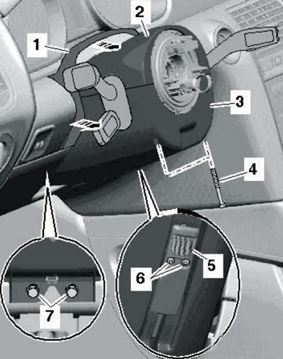
8.3. Removing the steering column covers.
Remove the bolts (4) with a T8 screwdriver, if present, remove the bolts (6) and remove the lever cover (5). Remove the bolts (7), separate the upper steering column cover (2) from the lower cover (3) and remove them. If present, disconnect the connector on the bottom cover.
4. Remove the bolt (2) and disconnect the connectors (1, 3, and 4). Before disconnecting the connector (4), discharge any static electricity from yourself. Carefully remove the switch assembly together with the steering column electronics control unit. Installation is carried out in reverse order.
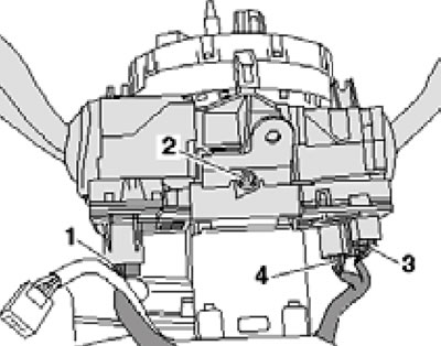
8.4. Removing the steering column switch unit.
Steering column electronic control unit
5. Remove the steering column switch assembly (see subsection above).
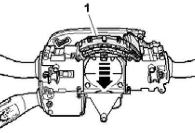
6. With the steering column in the central position, gently press the locks (arrows in the illustration) and separate the coil spring (2) with the angle sensor (1) from the steering column switch unit.
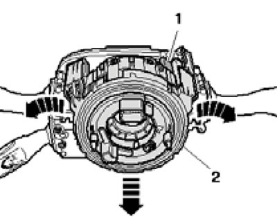
8.6. Removing the coil spring with the sensor.
7. Remove the bolts (see illustration) and remove the steering column electronics control unit (1) from the steering column switch assembly.
8.7. Fastening the steering column electronic control unit.
8. Installation is carried out in reverse order. After replacing the control unit, it should be recoded using a diagnostic tool (see chapter 5).
Coil spring and steering wheel angle sensor
9. Remove the steering wheel (see Chapter 9) and steering column pads (see paragraph 3).
10. Disconnect the upper connector of the coil spring, carefully press the clamps (see illustration) and remove the coil spring (1) from the steering column switch assembly.
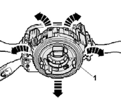
8.10. Removing the coil spring.
Note: For clarity, the steering column switch assembly is not shown in the illustration.
11. If necessary, after removing the coil spring, remove the steering wheel angle sensor in the direction of the arrow (see illustration).
8.11. Removing the steering wheel angle sensor.
After replacing the sensor, you should calibrate the sensor using a diagnostic tool (see Chapter 5).
12. Installation is carried out in reverse order.
Steering column switches
13. Remove the steering column switch assembly (see subsection above).
14. With the steering column in the central position, carefully press the locks (arrows in illustration 8.6) and separate the coil spring (2) with the angle sensor (1) from the steering column switch unit.
15. Remove the bolts (arrows in the illustration) and remove the steering column electronics control unit (2) and the right steering column switch (3), as well as the left lower steering column switch (1) from the steering column switch block.
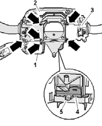
8.15. Removing the steering column switches.
Unscrew the bolts (5) and remove the holder (4).