



Table of contents: Steering column ↓ Removal and installation the… ↓ Removal and installation the… ↓ Checking the steering column for… ↓ Removal and installation the ELV… ↓ Removal and installation the safety… ↓
Steering column
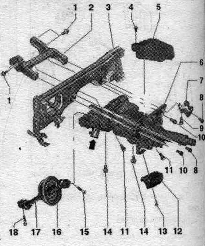
1. Bolt.
2. Support bracket.
3. Central pipe.
4. Bolt: 5 Nm.
5. ELV control unit "J764": After replacing the ELV control unit "J764", it is necessary to carry out the following work using the Tester, for this, select the appropriate program in the "guided functions" and follow the instructions on the display.
6. Steering column: depending on the steering wheel design (with or without dynamic steering) various steering column options are installed; the "arrow" regulator is installed on a car with dynamic control; do not unscrew or remove the "arrow" adjuster from the steering column; the regulator and steering column are a single unit and are replaced as an assembly; on the regulator "arrow" the "Safety lock of the system. active steering" (blocking magnet); when replacing the steering column with the regulator, it is necessary to carry out a basic adjustment of the system. dynamic steering: check for damage.
7. Right energy absorbing bracket space. for legs: determined depending on the sales market.
8. Bolt: 20 Nm. 2 pcs.; depending on the sales market, the right energy-absorbing bracket is also attached with this bolt. for the feet on the driver's side; observe the installation sequence during installation.
9. Bolt.
10/11. Bolt: 20 Nm, 2 pcs.; observe the sequence. installation during installation.
12. Pen.
13. Bolt: 3 Nm.
14. Bolt: 20 Nm, 2 pcs.; observe the installation sequence during installation.
15. Bolt: 30 Nm + 90°; replace when removed; always clean the threaded holes for bolts (for example, with a tap).
16. Seal cuff: align the positioning arrow to the 12 o'clock position.
17. Intermediate steering shaft.
18. Bolt: 30 Nm + 90°; replace when removed; always clean the threaded holes for bolts (for example, with a tap).
Removal and installation the intermediate steering shaft
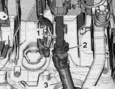
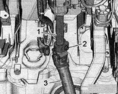
Set the wheels to the straight-ahead position. Adjust the steering wheel back and down as far as possible, using the full range of steering column adjustment. Set the steering wheel to the center position (front wheels in straight ahead position). Set the driver's seat all the way back. Unscrew bolt "2" and remove intermediate steering shaft "3" from steering column "1". Install the car on a lift.
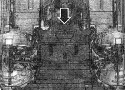
Remove the rear noise insulation "arrow".
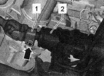
Unscrew the "arrow" bolt. Remove the steering intermediate shaft "1" from the steering gear "2".
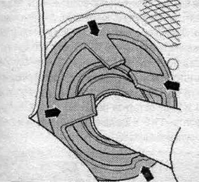
Remove the seal. the cuff is attached to the "arrow" pads from the body. Remove the intermediate steering shaft towards the interior.
Installation
Installation in reverse order. Always clean the threaded hole for the bolt (for example, with a tap). Install the intermediate steering shaft from the passenger compartment. Place the intermediate steering shaft "3" onto the steering column "1" until it stops and tighten the bolt "2". Insert the seal as far as possible. cuff "2". Make sure that arrow "1" is pointing vertically upwards.
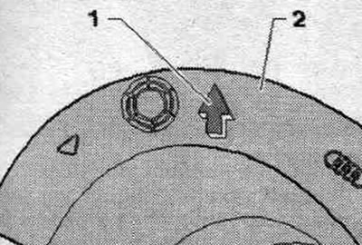
Pull the seal tight. cuff "1" through the hole. Fit the seal. cuff "1", without turning, completely onto flange "2". Check the installation. position of the sealing cuff according to the marking on the interior side. If necessary, loosen the seal. cuff and turn it to the correct mounting position. position. Next, place the intermediate steering shaft "1" onto the steering column "2" until it stops and tighten the bolt "arrow". Installation is in the reverse order.
Removal and installation the steering column
Attention! Before removing the steering wheel. column, do the following. Draw a diagram of the following elements: electrical wiring, electrical fastenings. wiring, places for installing cable ties. This is especially true for email. eLV control unit "J764" wiring. Before installing the steering wheel. column, do the following. Electrical gasket. the wiring must be performed in the same way as before removal. Attach the electrical wiring in the same manner as before removal. During the installation of the steering column, it is necessary to reinstall all cable ties that were removed or cut during dismantling. Check that the wiring of the ELV control unit "J764" is not pinched or comes into contact with sharp edges when adjusting the steering column. The steering column is supplied as a spare part only as an assembly. Repair is not possible. Only the ELV control unit "J764" can be replaced individually.
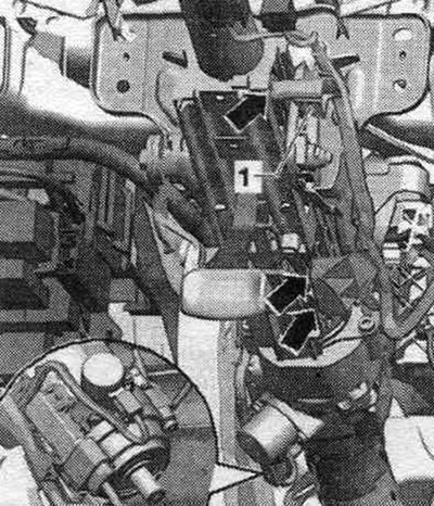
Set the wheels to the straight-ahead position. Adjust the steering wheel back and down as far as possible, using the full range of steering column adjustment. Remove the driver's airbag. Remove the steering wheel from the airbag. Remove the instrument panel trim on the driver's side. If present, remove the right driver's side footwell energy absorber. Remove the air vent deflector. for the feet on the driver's side. Remove the steering column trim. Remove the steering column switch module (SMLS). On steering columns with dynamic steering, do not loosen or remove the dynamic steering assembly bolts. Remove the cable guide "1" from the steering column "arrow" and set it aside. On vehicles with dynamic steering, disconnect the controller plug connectors and release the cable guide on the left side of the steering column.
Unscrew bolt "2" and remove intermediate steering shaft "3" from steering column "1".
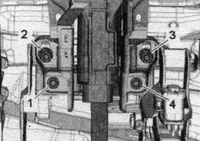
Unscrew the bolts "1...4" of the steering column from below on the support bracket and on the pedal bracket.
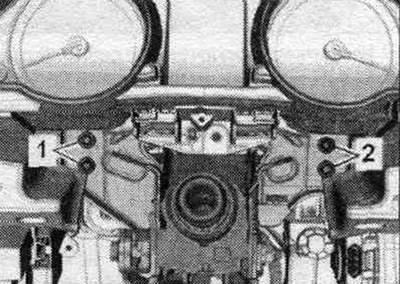
Unscrew bolts "1" and "2" of the steering column from the central pipe, while supporting the column with your hand from below. Pull the steering column back slightly, remove it from the centering holes of the central pipe and lower it down.
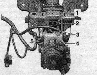
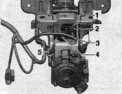
Disconnect the electrical. plug connector "2" of the ELV control unit "J764" "1", remove the retainer "5", release the wiring harness "3" and remove the steering wheel. column.
Installation
Installation in reverse order. When replacing the steering column, use the ELV control unit mounting bolt supplied with the new steering column "J764". Clean the threaded hole before installing the new bolt "2" (for example, with a tap). After connecting the plug connector "2", make sure that the wire harness "3" is secured with the clamp "5" in the place provided for this purpose. Make sure that the wiring harness "3" of the ELV control unit "J764" "1" is not pinched or touches sharp edges when moving the steering column.
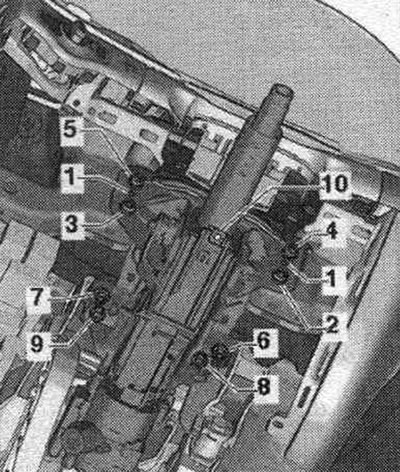
Insert the mounting tabs "1" of the steering column into the mounting holes on the center tube. Tighten all bolts, but do not tighten. First tighten bolt "2" to the specified torque. tightening. Then tighten bolt "3" to the specified torque. tightening. Then tighten bolt "4" and bolt "5" to the specified torque. tightening. If equipped, install the right energy absorbing element in the driver's side footwell. Lastly, tighten bolt "6" and bolt "7" to the specified torque. tightening. Tighten bolt "8" and bolt "9" to the specified torque. tightening. When replacing the steering column, replace nut "10".
Place the intermediate steering shaft "3" onto the steering column "1" until it stops and tighten the bolt "2". Install the steering column switching module (SMLS). Install the steering column trim. Install the space deflector. for the feet on the driver's side. Install the driver's side dashboard trim. Install the steering wheel with airbag. Install the driver's airbag. After replacing the ELV "J764" control unit, it is necessary to adapt the control unit in the immobilizer. If the same steering column and the same ELV control unit "J764" are being installed, there is no need to re-adapt the ELV control unit "J764." Connect the "VAS 5052" diagnostic system and activate the "Guided Functions" mode using the vehicle-specific entry mode. Select the appropriate program in "Guided Functions." Follow the on-screen instructions. After installing the steering column switch module (SMLS), calibrate the G85 steering angle sensor. Connect the VAS 5052 diagnostic system and activate the "Guided Functions" mode using the vehicle-specific entry mode. Follow the on-screen instructions.
Checking the steering column for damage
Check that the steering column is free of binding and rotates easily. Check the ability to easily adjust the steering column in length and height. Check that there is no movement of the pipe "in the direction of arrow A" or "in the direction of arrow B".
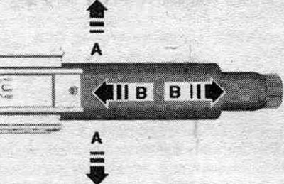
If the pipe moves, the steering wheel should be replaced. column.
Removal and installation the ELV "J764" control unit
To replace the ELV "J764" control unit, simply remove the following parts from the steering column: driver's airbag, steering wheel, steering column trim, necessary electrical wires and plug connectors. Remove the steering column. Unscrew bolt "1" and remove the ELV control unit "2".
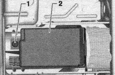
Installation
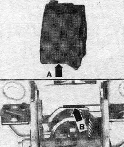
Installation in reverse order. When replacing only the ELV control unit "J764", the previously installed control unit mounting bolt must be reused. When replacing the steering column, it is necessary to remove the protective cover and use the ELV control unit mounting bolt "J764" supplied with the new steering column. When installing the ELV control unit, insert the "arrow A" pin into the "arrow B" groove of the steering column.
After connecting the plug connector "2", make sure that the wire harness "3" is secured with the clamp "5" in the place provided for this purpose. Make sure that the wiring harness "3" of the ELV control unit "J764" "1" is not pinched or touches sharp edges when moving the steering column.
After replacing the ELV "J764" control unit, follow these steps using the Tester. To do this, select the appropriate program in the "Guided Functions" and follow the instructions on the display. If the steering angle sensor "G85" indicator lamp lights up after replacement, troubleshoot the fault using the "Guided Fault Finding" mode on the VAS 5051 B diagnostic system. If necessary, recalibrate the system.
Removal and installation the safety interlock system. active steering (blocking magnet)
When the locking magnet is removed, do not turn the steering wheel or change the straight-ahead position or the steering angle. wheels. Otherwise, after finishing the work, this may lead to a distortion of the steering wheel position. Set the steering wheel to the straight ahead position (front and rear wheels. the axles should be aligned) and, if possible, the steering wheel lock should be fixed in the straight ahead position. Turn off the ignition. Designate mont. position and the position of the locking magnet "arrow" is necessary for subsequent assembly). Remove the plug connection "4" from the locking magnet "3". Clean the head ("star") of the bolts "1 and 2" from the remains of thread lock. Unscrew bolts "1 and 2" and remove the locking magnet "3" from the steering column.
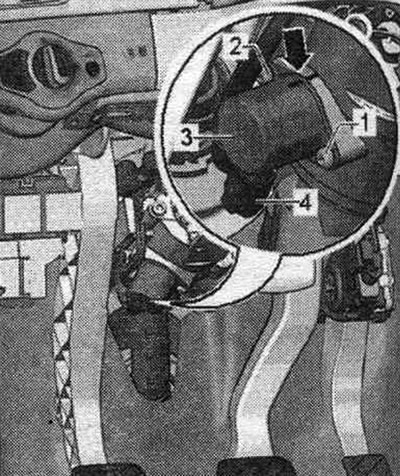
Installation
Installation in reverse order. After replacing the blocking magnet, you should update the software of the system control unit. active steering "J792", for this purpose, run the corresponding program on the diagnostic complex. When installing a new blocking magnet, the markings from the old blocking magnet should be transferred to the new one. Install the new locking magnet according to the markings made before removal and, as shown in the following table, secure with both new bolts "1 and 2" (using the included tool).
| Subsequence | Bolt number | Tightening torque |
| 1 | 1 | 2 + 2 Nm |
| 2 | 2 | 4 + 2 Nm |
| 3 | 1 | 8 + 2 Nm |
| 4 | 2 | 8 + 2 Nm |
Connect the plug connection to the locking magnet. Clear event memory. Carry out an initialization drive - to do this, turn the steering wheel approx. 45° left/right from straight ahead position.