
Table of contents: Power steering repair ↓ Removal and installation of el. mag.… ↓ Removal and installation the… ↓ Removal and installation transverse… ↓ Removal and installation the… ↓ Checking the working level. power… ↓ Bleeding the steering wheel after… ↓ Checking the steering wheel for leaks ↓
Power steering repair
Replace self-locking nuts and screws. Carrying out welding and straightening works on steering wheel parts. mechanism is not allowed. To lubricate the rack, use only steering wheel grease. mechanism.
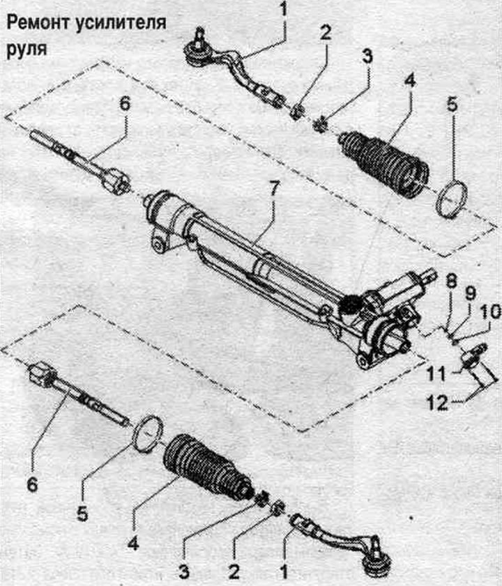
1. Cross-rudder tip. rods: various designs with a hinge pin with a long or short thread; check that the boot is seated correctly and that there is no damage. When replacing, make sure that the thread on the steering wheel tip is correct. the thrust was long enough (there should be enough free threads left, about 5 mm). Otherwise, it is necessary to install a tip with a longer thread on the hinge pin.
2. Nut: 60 Nm.
3. Spring clamp: replace when removed.
4. Corrugated cover: check for damage; check for twisting after adjusting the wheel alignment; replacement is possible without removing the steering wheel. mechanism.
5. Clamp: replace when removed.
6. Transverse thrust: 90 Nm; lubricate the joint with steering wheel grease. mechanisms.
7. Power steering: lubricate the rack and pinion with steering wheel grease. mechanisms.
8. Sieve: replace when removed.
9. Sealing ring: replace when removed.
10. Sealing ring: replace when removed.
11. Solenoid valve for Servotronie "N119"; the following values can be queried using the "VAS 5051": speed signal, electrical supply to on-board power supply control unit 2 "J520", electrical status. magnetic valves, values of control currents of the el. magnetic valves; connect the "VAS 5051" and in the "Function/Component Selection" section, select the "Troubleshooting" function, then "Body", "Electrical Equipment", "01 - Systems with Self-Diagnostics Function", "J520 - On-Board Network Control Unit 2", "Electrical Components", "N119 - Servotronic Valve".
12. Bolt: 3 Nm. Be sure to follow the sequence. tightening the bolts.
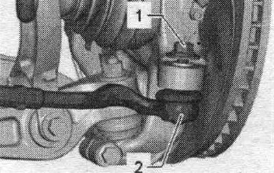
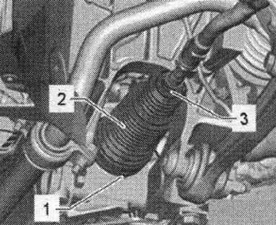
Removal and installation of el. mag. Servotronie valve "N119"
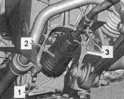
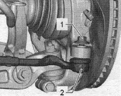
Replacement is only possible with the steering mechanism removed. Remove the steering gear. Clean the steering wheel thoroughly. mechanism "6" in the el. area. magnetic valve "3". Make sure that dirt does not get into the steering wheel. mechanism "6". Disconnect plug connection "8". Prevent dirt from getting into connector "8". Unscrew bolts "1" and "2". Remove solenoid valve "3" from steering gear "6". Remove mesh filter "7" from steering gear "6", clean steering gear if necessary. mechanism.
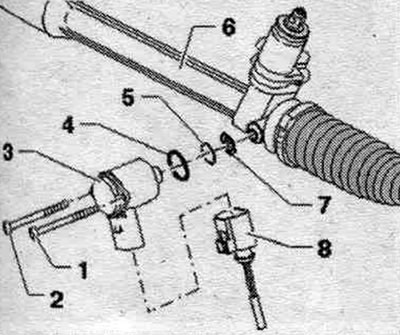
Installation
Installation in reverse order. Insert a new mesh filter "7". Lubricate the sealing rings "4" and "5" with a thin layer of steering wheel grease. mechanism and install. Insert email. mag. valve "3" all the way to the steering wheel. mechanism "6". Do not distort the el. magnetic valve.
Tighten bolts "1" and "2" as follows:
- Tighten bolt "1" to a torque of 0.5 Nm.
- Tighten bolt "2" to 1.5 Nm.
- Tighten bolt "1" to 3.0 Nm.
- Tighten bolt "2" to 3.0 Nm.
Install steering wheel. mechanism.
Steering wheel adjustment. mechanism with hydraulic control
Adjustment is carried out with the engine off. Remove sound insulation. Set the power steering mechanism to the center position. When alternately moving the steering wheel right and left (approximately 30° from the middle position) in case of too much play in the steering wheel. a knocking sound is heard in the mechanism. At the same time, the 2nd mechanic carefully turns the adjusting screw "arrow" until the knocking sound in the car's interior disappears.
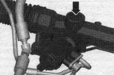
Take a test drive. At the same time, after maneuvering or turning a corner, the steering system should automatically, without jamming, set the steered wheels straight. Adjust the adjustment if necessary.
Removal and installation the transverse steering column tip. traction
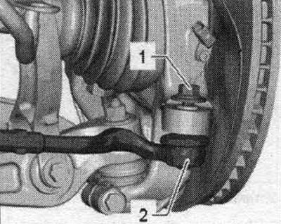
Two different rudder tip housings were installed as standard. rods, they differ in the length of the thread on the hinge pin. When replacing the transverse steering tip. traction, ensure that the thread length on the end of the transverse steering wheel is sufficient. traction (it is necessary to ensure a sufficient number of free threads, approx. 5 mm) Otherwise, it is necessary to install a new cross-bar end. rods with a longer thread on the hinge pin. Place the car on a lift. Remove the wheel. Measure and record the dimension "a" between the tip. transverse rudder. rods "2" and transverse steering rod "1" on the left and right. The size of "a" after installation on the left and right should be the same. If necessary, the "Longer" crossbar tip should be shortened. rods (screw deeper into the transverse steering wheel. traction).
Unscrew nut "1" of the cross steering wheel tip pin. rod "2" until it is flush with the thread of the finger. When loosening, if necessary, hold it from turning.
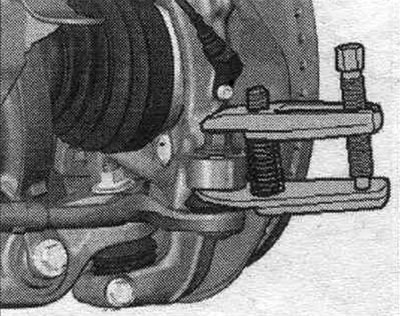
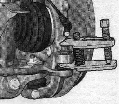
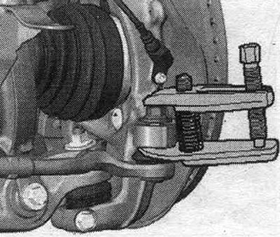
To protect the threads, leave the nut on the pin screwed on for a few turns. Press out the crossbar tip. remove the rods from the hub bearing housing using the T40010 A ball joint puller. Then unscrew the nut. Make sure that both arms of the puller lever are parallel to each other at the moment of maximum force application; correct the position if necessary.
Just loosen nut "2". At the same time, hold the tip of the transverse steering wheel. rods "3" from turning. Unscrew the end of the transverse steering wheel. traction "3".
Installation
Installation in reverse order. Screw on the crossbar tip. rods "2" on the transverse steering. rod "1" so that dimension "a" corresponds to the value during removal. Align the crossbar tip. rods "2" so that the finger fits into the mounting. position. Install the crossbar tip. thrust into the hub bearing housing until it stops. Tighten nut "1". If necessary, hold it to prevent it from turning while tightening. Tighten nut "2". Install the wheel and tighten the mounting bolts.
Removal and installation transverse steering wheels. traction
Transverse rudders. the rods can be removed and installed without dismantling the steering wheel. Place the car on a lift. Remove the wheel. Remove sound insulation. Measure and record the dimension "a" between the tip of the crossbar. rods "2" and transverse steering rod "1" on the left and right. The size of "a" after installation on the left and right should be the same. If necessary, the "Longer" crossbar tip should be shortened. rods (screw deeper into the transverse steering wheel. pull rod). Clean the power steering mechanism and subframe in the area of the corrugated gaiter. When replacing the transverse steering wheel. do not allow dirt to enter the power steering mechanism and the corrugated boot.
Open and remove spring clamp "3" using hose clamp pliers. Remove clamp "1" and remove bellows "2" outward from the power steering mechanism.
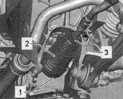
Unscrew nut "1" of the cross steering wheel tip pin. rod "2" until it is flush with the thread of the finger. When loosening, if necessary, hold it from turning. To protect the threads, leave the nut on the pin screwed on for a few turns.
Press out the crossbar tip. remove the rods from the hub bearing housing using the T40010 A ball joint puller. Then unscrew the nut. Make sure that both arms of the puller lever are parallel to each other at the moment of maximum force application; correct the position if necessary.
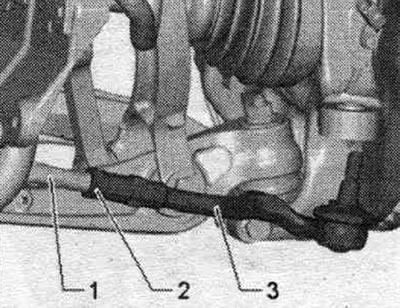
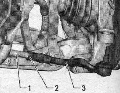
Unscrew the steering wheel. thrust. At the same time, hold the steering piston rod. mechanism with a booster using the wrench "1".
2. Wrench - insert "VAG 1923"
Installation
Installation in reverse order. Tighten the steering wheel. traction using a wrench - insert "VAG 1923" "2". At the same time, hold the steering piston rod. mechanism with a booster using wrench "1". Replace spring clamp "3" and clamp clamp "1".
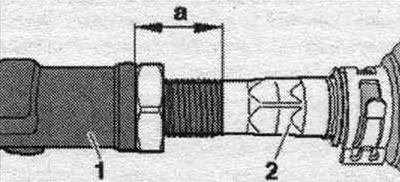
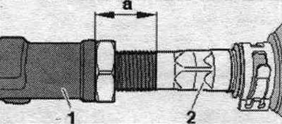
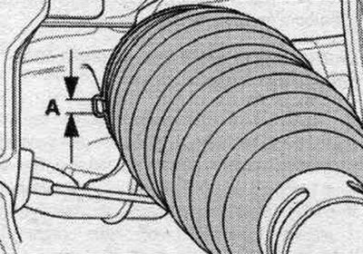
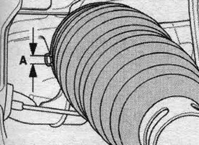
Installing the clamp: Ensure that dimension "A" is maintained at a maximum of 5.7 mm. Dimension "A" must not exceed 5.7 mm, otherwise sealing problems will occur. Install the new clamp and tighten it with steering wheel pliers. mechanism "VAS 6199". First turn the transverse steering wheel. the rod so that the rod end journal is in the installation position.
Install the transverse steering wheel. thrust into the hub bearing housing until it stops. Install the wheel and tighten the mounting bolts.
Removal and installation the corrugated cover
If the steering wheel boot is damaged. the mechanism gets exposed to moisture and dirt. There should be a film of grease on the rack teeth that can be felt by touch. If there is no lubricating film, the steering gear must be replaced. The steering gear is also replaced in case of corrosion, damage or wear of the toothed rack. Place the car on a lift. Remove the wheel. Set the steering wheel to the "straight ahead" position. Remove the sound insulation. Clean the power steering mechanism and subframe in the area of the corrugated boot. Unscrew nut "1" of the cross steering wheel tip pin. rod "2" until it is flush with the thread of the finger. When loosening, if necessary, hold it from turning. To protect the threads, leave the nut on the pin screwed on for a few turns.
Press out the crossbar tip. remove the rods from the hub bearing housing using the T40010 A ball joint puller. Then unscrew the nut. Make sure that both arms of the puller lever are parallel to each other at the moment of maximum force application; correct the position if necessary.
For subsequent installation, mark the position of nut "2" on the tie rod "1". Hold the steering rod end from turning. rods "3", loosen nut "2".
Open and remove spring clamp "3" using hose clamp pliers. Remove clamp "1" and remove bellows "2" outward from the power steering mechanism.
Unscrew the end of the transverse steering wheel. rods "3" and nut "2" from the transverse steering. rods "1". Pull the corrugated boot together with the spring clamp from the transverse steering wheel. traction.
Installation
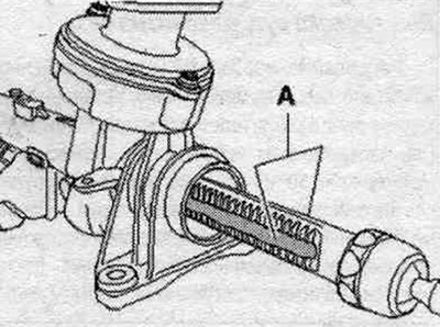
Before installation, apply the grease supplied with the repair kit to the toothed rack. It is strictly forbidden to use any other lubricant. To do this, turn the steering mechanism in both directions until it stops. For better clarity, see the figure the steering wheel is shown removed. mechanism. Apply grease to the rack on the side of the teeth "A" and on the side of the pressure stop. Set the steering wheel to the "straight ahead" position. Place it on the crossbar. new clamps and corrugated cover for the rod.
Screw on nut "1" and the crossbar tip. rods "3" to the marking applied before removal. Tighten nut "2" with a torque wrench. At the same time, hold the tip of the transverse steering wheel. rods "3" from turning. The sealing surfaces of the bellows/power steering mechanism must be degreased during installation. Slide the corrugated boot with the new clamp onto the steering gear housing. Ensure that the corrugated boot is correctly positioned on the power steering mechanism. The corrugated boot should fit into the groove and around the perimeter of the power steering mechanism.
Installing the clamp: Ensure that dimension "A" is maintained at a maximum of 5.7 mm. Dimension "A" must not exceed 5.7 mm, otherwise sealing problems will occur.
Clamp clamp "1" using the VAS 6199 steering gear clamp pliers. Secure spring clamp "3" to bellows "2" using hose clamp pliers. Installation in reverse order. The need to adjust the wheel alignment angles.
Checking the working level. power steering fluid
Do not start the engine and set the front wheels straight ahead. The oil should be cold (approx. 20°C). Unscrew the cap. Wipe the oil level dipstick with a clean cloth. Tighten the lid by hand and unscrew it again. Applies only to measuring the oil level with the cap previously closed. Check the oil level: the oil level should be in zone "A".
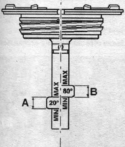
The oil is in working condition (approx. 80°C). Unscrew the cap. Wipe the oil level dipstick with a clean cloth. Tighten the lid by hand and unscrew it again. Applies only to measuring the oil level with the cap previously closed. Check the oil level: the oil level should be in zone "8". If the oil level is above the specified zone, pump out the oil. If the oil level is below the specified zone, it is necessary to check the hydraulics. system for leaks. In this case, adding oil alone is not enough. Do not reuse drained hydraulic oil.
Bleeding the steering wheel after reinstallation
After performing the steering wheel reinstallation work, it is necessary to bleed air from the steering wheel in different ways, depending on the scope of the reinstallation work.
Bleeding after complete steering wheel replacement or steering wheel replacement. mechanism
Fill the expansion tank completely. reservoir. Raise the car so that all wheels hang freely. Turn off the engine. With the engine off, turn the steering wheel 10 times from lock to lock. Fill the expansion tank completely. tank. Run the engine for a short time (no more than 2 seconds). The pump must not suck in air. The steering wheel must not be turned under any circumstances. Pauses between individual engine starts are approximately 30 seconds. Check the hydraulic oil level. system and top up if necessary. Repeat this procedure until the oil level is fixed at one mark. With the engine off, turn the steering wheel 10 times from lock to lock. Check hydraulic oil level. system and top up if necessary. Start the engine. Turn the steering wheel 10 times from lock to lock. Check hydraulic oil level. system and top up if necessary. Possibly remaining in the system. the air in the steering wheel will come out on its own after 10...20 km of driving.
Bleeding air after reinstalling one steering wheel assembly, except for the steering wheel. mechanism
Check hydraulic oil level. system and top up if necessary. Run the engine for a short time (no more than 2 seconds). The pump should not suck in air, and the steering wheel should not be turned under any circumstances. Pauses between individual engine starts are approximately 30 seconds. Check the hydraulic oil level. system and top up if necessary. Repeat this procedure until the oil level is fixed at one mark. Start the engine and let it run for 2-3 minutes, do not turn the steering wheel. Possibly remaining in the system. the air in the steering wheel will come out on its own after 10...20 km of driving.
Checking the steering wheel for leaks
It is necessary to check the tightness of the steering wheel after installation work and in the absence of hydraulic fluid in the expansion tank. tank. Remove the sound insulation. Start the engine. Turn the steering wheel in both directions until it stops and hold it there briefly. At the same time, in the system. the maximum possible pressure is created. To avoid damaging the pump during this test, the steering wheel should not be held in the extreme position for more than 10 seconds. In this position, the following parts should be checked for leaks: the steering wheel valve body seal ring. mechanism, all pipeline connections, all main line connections, vane pump, gear rack sealing rings. This check is carried out only with the anthers moved back. Open the spring band clamp and the boot clamp. Move the corrugated cover back. If in the steering wheel housing. if there is visible oil in the mechanism and/or oil is visible in the anthers, then the steering mechanism must be replaced.
(The original article is available on the website «AUDIMANUAL.RU»)