
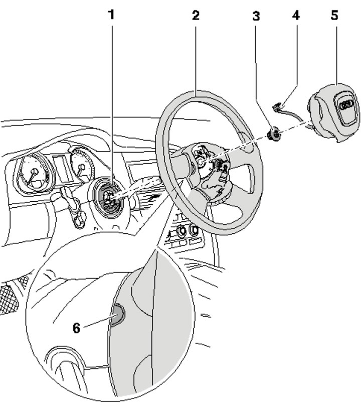
14.1a. Steering wheel parts:
1 - Spiral spring;
2 - Steering wheel;
3 - Bolt, subject to replacement, 50 Nm;
4 - Coil spring connector;
5 - Front passenger airbag module;
6 - Plugs for mounting bolts of module 5, 2 pcs.
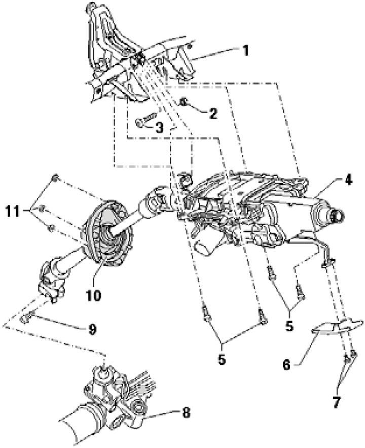
14.1b. Steering column parts:
1 - Cross beam for mounting the steering column;
2 - Self-locking nut, replaceable, 20 Nm;
3 - Bolt;
4 - Steering column, can only be replaced as an assembly;
5 - Bolt, 20 Nm;
6 - Handle;
7 - Bolt, 4.5 Nm;
8 - Steering mechanism;
9 - Bolt, to be replaced, 35 Nm, then tighten to an angle of 90°;
10 - Seal;
11 - Self-locking nut, replaceable, 4 Nm.
The steering column is supplied as a spare part only as an assembly. Steering column repair is not provided.
2. Remove the driver's airbag (see Chapter 11).
3. Set the front wheels to the straight-ahead position. Remove the bolt (2 in the illustration), mark the position of the steering wheel relative to the steering column (to facilitate installation) and remove the steering wheel (3).
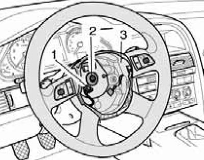
14.3. Bolt (2) and connectors (1) of the steering wheel (3).
Once the steering wheel has been removed, the steering column can be removed as described below.
4. Remove the driver's footwell cover (see Chapter 10).
5. Remove the bolts (1 in the illustration) and remove the handle.
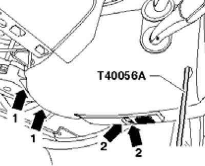
14.5. Removing the steering column cover.
Then unscrew the rear bolts (1), unscrew the front bolts with a T8 (T40056A) screwdriver and remove the steering column cover.
6. Remove the front sound insulation panel under the engine compartment (see Section 19 of Chapter 1).
7. Unscrew the two bolts and remove the steering gear heat shield (And in illustration 4.43 of Chapter 2). Turn the steering gear pinion half a turn, unscrew the steering gear hinge bolt (B) and carefully press the lower shaft of the column into the upper shaft until it stops.
Note: On some models, the top nuts are also accessible from the engine compartment from above.
8. On 4.2 TDI engines, remove the left catalytic converter (see Chapter 4).
9. Slightly move the left heat shield to the side and unscrew the three nuts securing the seal (see illustration).
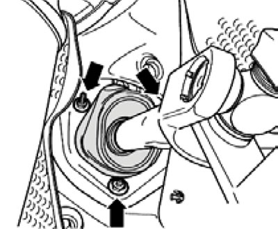
14.9. Seal fastening.
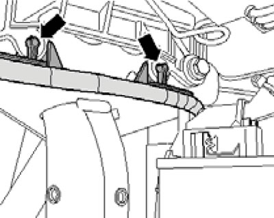
10. Remove the bolts (1 in the illustration), remove the beam (1) and at the same time remove the electrical wiring.
14.10. Beam fastening bolts.
11. Disconnect the connector (2 in the illustration) and remove the bracket (1) from the control unit.
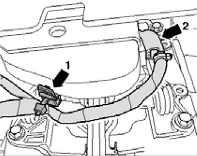
14.11. Electrical wiring connector and bracket.
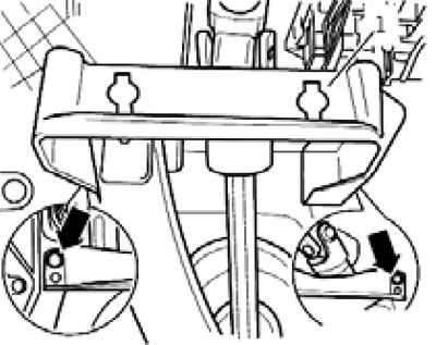
12. Release the electrical wiring on the left side (see illustration).
14.12. Electrical wiring clamps on the left.
13. On models with electric steering column adjustment, disconnect the connector (1 in the illustration).
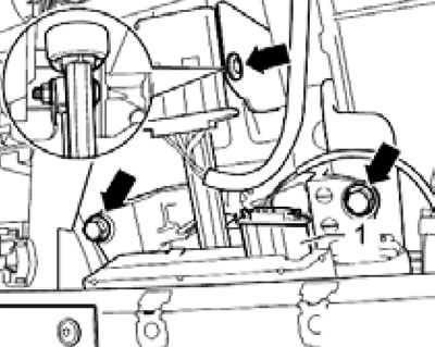
14.13. Connector (1) and bolts (arrows) of the steering column.
Remove the bolts (arrows).
14. Disconnect the connectors (1 and 3 in the illustration).
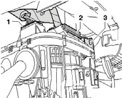
14.14. Connectors (1 and 3) and guide (2) for electrical wiring.
Pull the wiring guide (2) up from the steering column.
15. Remove the bolts (arrows in the illustration), then bolt (1) and finally bolt (2).
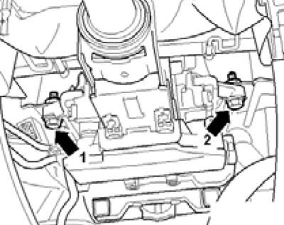
14.15. Steering column fastening.
Carefully remove the steering column.
16. The steering column should be carried with both hands, without bending it, holding it by the top and in the hinge area (see illustration).
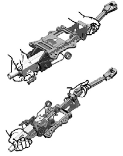
14.16. Correct transfer of the steering column.
Do not carry the steering column by its lever, springs or deformable element. Do not carry or lift the steering column by the shaft with one hand. Do not bend the joint more than 90°. The new steering column comes with a transport protector.
17. Replace the seal if necessary. To do this, clamp the steering column in a vice as shown in the illustration, mark the position of its upper and lower parts relative to each other, pull the lower part out of the upper part with a strong jerk in the direction of the arrow and remove the seal from the lower part.
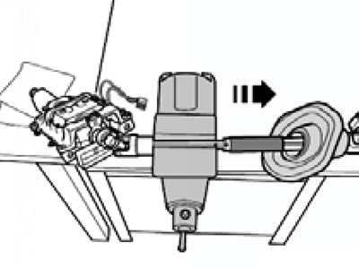
14.17. Separating the steering column.
If the guide surface on the bottom of the column is dirty and nicked, the steering column should be replaced, as optimal sealing of the seal to the column will not be guaranteed. Slide the seal onto the bottom of the column, rotating the seal slightly. Assemble the column according to the marks made during removal. If the column is assembled correctly, its lower part should not separate from the upper part without applying additional force.
18. Check the ease and smoothness of rotation of the steering column, as well as the possibility of its adjustment. If there is a gap (arrow in the illustration) between the slider (1) and bracket (2) exceeds 0.5 mm, the steering column should be replaced.
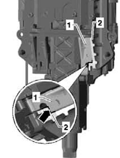
14.18. Gap between the slider and the bracket.
19. Installation is carried out in reverse order. Please note the following features.
20. When replacing a steering column with a mechanical adjustment drive, transfer the adjustment lever to the new column.
21. When installing the steering column, first tighten all its fasteners by hand, then finally tighten the bolts (1-4 in the illustration) and finally tighten the nut (5).
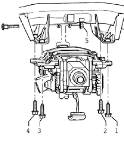
14.21. Steering column fastener tightening sequence.
22. After installing the new steering column, adapt the new authorization module "J518" to the existing immobilizer, code the module "J518" and apply the basic settings for the steering wheel angle sensor "G85".
23. When installing the steering wheel, align the marks made during removal. If installing a new steering wheel, make sure the front wheels are straight and position the steering wheel straight as well.
[This article was previously published on the resource «audimanual.ru»]