
Table of contents: Removal and installation the travel… ↓ Measuring the steering gear stroke ↓ Removal and installation tie rod ends ↓ Removal and installation steering… ↓
1. The steering gear assembly parts are shown in the illustration.
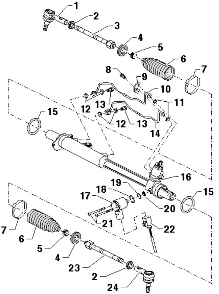
16.1. Steering gear assembly parts:
1 - Right tie rod end, with "R" mark or arrow pointing forward;
2 - Nut, 70 Nm;
3 - Right rod, 100 Nm;
4 - Travel limiter, only on long stroke mechanism;
5 - Spring clamp;
6 - Anther;
7 - Clamp, subject to replacement;
8 - Bolt, 12 Nm;
9 - Locking plate;
10, 14 - Control connection;
11, 15 - Sealing ring, subject to replacement;
12, 18, 19 - Gasket, subject to replacement;
13 - Hollow bolt, 40 Nm;
16 - Steering mechanism;
17 - Solenoid valve "Servotronic" N119;
20 - Mesh filter;
21 - Bolt;
22 - Electrical wiring connector;
23 - Left rod, 100 Nm;
24 - Left tie rod end, marked "L" or with an arrow pointing forward.
Removal and installation the travel limiter
2. Place the car on a lift and remove the front wheel.
3. Clean the steering gear in the boot area. Check the condition of the boot. Open the clamp and slide the boot back.
4. Unscrew the rod (see illustration).
16.4. Turning out the steering rod.
5. Remove the travel limiter (1 in the illustration).
16.5. Travel limiter (1).
6. Installation is carried out in reverse order. Large contact surface of the limiter (arrows in illustration 16.5) should be facing the rod, and the bushing (1) should be facing the steering gear (2). Finally, check the wheel alignment angles.
Measuring the steering gear stroke
7. The steering gear stroke can be measured using a diagnostic tool. To do this, select "Function/component selection" → "Fault finding" → "Running gear (Rep. Gr. 01; 40 - 49)" → "Brake system (Rep.-Gr. 01; 45 - 47)" → "01 - Self-diagnosis compatible systems" → "Brake electronics ABS and ESP" → "Electrical components" → "G85 Steering travel measurement". If the value measured in this way is outside the permissible limits, measure the stroke directly as described below.
8. Place the vehicle on a lift and remove the left boot from the steering gear. Turn the wheels all the way to the right.
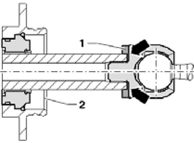
9. On a steering gear with a travel limiter, the distance (and in the illustration) should be 144.6 mm.
16.9. Steering gear travel with limiter.
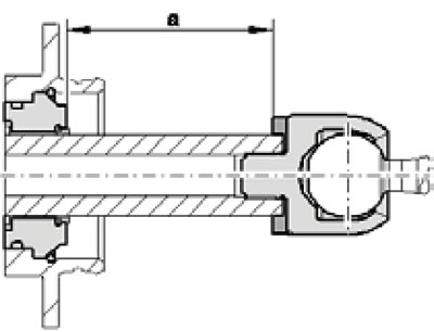
10. On a steering gear without a travel limiter, the distance (and in the illustration) should be 152.6 mm.
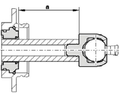
16.10. Steering gear travel without limiter.
11. If the measured distance does not match the specified one, remove the right boot from the steering gear and turn the wheels all the way to the left. Repeat the measurement on the left side and make sure the result matches the measurement on the right side.
Removal and installation tie rod ends
12. Place the car on a lift and remove the wheel.
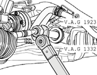
13. Loosen the locknut (1 in the illustration), holding the rod by the flats (1). Loosen the nut (4), press the tip out of the steering knuckle (see Figure 7.8 in Chapter 7), finally remove the nut (4) and separate the tip (3) from the steering knuckle.
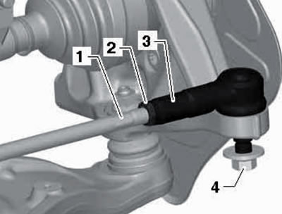
16.13. Tie rod end fastening parts.
Unscrew the tip from the rod, holding it by the hexagon (4).
14. Remove grease from the pin and the mounting hole in the steering knuckle. Choose the correct tip: the one with the correct letter or the one with the arrow facing forward.
15. Screw the tip onto the rod until it stops, insert the tip into the steering knuckle and tighten the fasteners.
16. Install the wheel and check the front wheel alignment angles.
Removal and installation steering rods
Note: Left and right rods are the same.
17. Place the car on a lift and remove the front wheel.
18. Clean the steering gear in the boot area. Check the condition of the boot. Open the clamp and slide the boot back. Check if the travel limiter is installed (1 in illustration 16.5).
19. Ease the pull (see illustration 16.4).
20. Separate the tie rod end from the steering knuckle (see Figure 7.8 in Chapter 7) and finally unscrew the rod.
21. Installation is carried out in reverse order. Immediately tighten the tie rod to 100 Nm. Finally, check the front wheel alignment.