
Removal
1. Disconnect the ground wire from the battery. Access to the steering rack with the engine installed is very difficult, and it is not easy to make it easier.
2. Release the fasteners, then remove the cover of the shelf at the rear of the engine compartment.
3. Remove the battery as described in chapter 5A.
4. Loosen the mounting bolts and remove the battery shelf.
5. Remove the air filter and air ducts as described in the appropriate section chapters 4.
6. Remove the trim panels under the driver's side fascia to access the base of the steering column.
7. Tie the upper and lower sections of the column together with wire. This is necessary to prevent them from falling apart when the column is removed from the steering shaft.
Warning: When removing the steering column from the steering gear, do not allow it to separate into sections - the alignment of the internal components will be disrupted.
8. Loosen the nut of the clamp bolt securing the joint to the steering gear shaft. Turn the bolt half a turn and remove it from the clamp.
9. Pull the steering column joint off the steering shaft and set it aside. Separate the plastic trim from the engine shield and pull it into the passenger compartment.
10. Apply the handbrake, raise the front of the car and install safety supports. Remove both front wheels. When removing the wheels, tighten one bolt into the hubs to prevent the brake discs from shifting.
11. Remove the right steering knuckle as described in items 1...10 and paragraph 2 of this chapter. Try not to damage the rubber boots of the steering tips when removing.
12. Disconnect the lower part of the right suspension strut from the lower suspension arm as described in paragraph 3, but do not loosen the upper support nuts.
13. Remove the three bolts and remove the upper control arm mounting bracket, strut tower and both control arms as a unit from the right wheel arch. The bolts are accessible through the shelf at the rear of the engine compartment. There may be plastic washers under the bolt heads. These are factory installed components and do not require reinstallation after removal.
Note: Remember the location of all washers under the bolt heads; they must be installed in their proper places during assembly so as not to disturb the adjustment of the front wheel alignment angles.
14. Unscrew the plastic nut, unhook the latches and remove the part of the mudguard that covers the window in the body for the passage of the steering rod to the steering knuckle.
15. Clamp the hoses at the power steering reserve tank with clamps or clips. This will minimize fluid loss during subsequent operations.
16. Apply markings to facilitate assembly, unscrew the bolts connecting the tubes to the steering gear: be prepared for a liquid spill - put a suitable container under it. Disconnect both tubes and remove the sealing washers. Discard the washers - new ones are required for installation. Plug the holes so that the liquid does not leak out and dirt does not get into the system.
17. Release the tubes from the fasteners and move them away from the steering mechanism.
18. Remove the heat shield from the front of the steering gear.
19. On models with air conditioning, disconnect the wiring connector from the pressure sensor on the steering gear housing.
20. Unscrew the steering gear mounting bolts. There are three bolts in total: two on both sides of the shaft housing on the right side of the mechanism (one is accessible from the top of the case, the other from the bottom). The third bolt is located to the left of the steering gear and can be accessed from above through a shelf in the rear of the engine compartment.
21. Remember the correct routing of all hoses and wiring.
22. With the help of an assistant, free the steering gear from the engine shield and take it out through the right arch, removing it from the car. Try not to damage the hoses, wiring and rubber boots.
23. After removing the steering gear, make sure that its covers are not damaged and, if necessary, replace them (fig. 17.23).
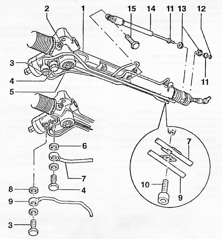
Fig. 17.23. Steering gear and its components - right-hand drive models: 1. Steering mechanism; 2. Inspection hole with plug; 3. Connecting bolt (hollow); 4. Connecting bolt (hollow); 5. Adjusting screw; 6. Sealing washer; 7. Return pipe; 8. Sealing ring; 9. Feeding tube; 10. Bolt; 11. Bushing; 12. Nut; 13. Bushing; 14. Damper; 15. Bolt
Repair
24. Make sure there is no wear or damage to the steering mechanism. The rack should move freely and smoothly throughout its entire travel, without any noticeable play or jamming. Make sure there is no damage or leakage to the hydraulic connections of the mechanism and that the connecting bolts are securely tightened.
25. Repair of the mechanism with replacement of damaged components is possible, but it is better to have this operation completed by an Audi/VAG dealer. You can replace the covers and steering rod joints yourself. Repair procedures are described in many sections of this chapter.
Installation
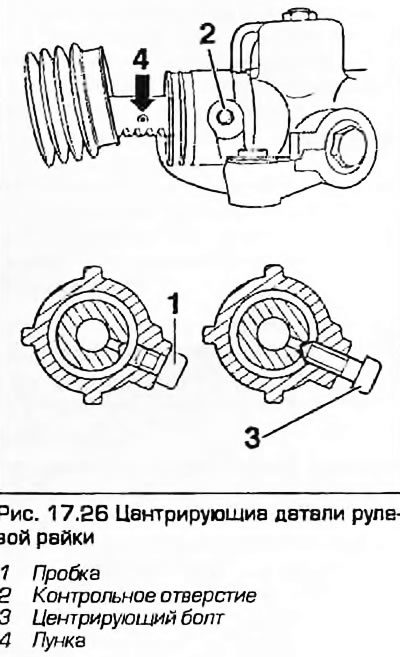
26. Before installation, the rack must be centered. Unscrew the plug with the internal hexagon from the inspection hole on the side of the mechanism housing. Move the right steering rod by hand so that the hole on the rack is visible in the inspection hole. Take a bolt with the same thread as the plug and sharpen it to a cone. Screw the bolt into the housing so that its cone enters the hole in the rack. Check the fixation of the rack by pulling it by the rods. The rack has taken the middle position (fig. 17.26).
27. Together with an assistant, install the mechanism in place, trying not to damage the hoses and wiring, and lay them out correctly.
28. Tighten the two rack mounting bolts that are accessible from above, but tighten them only "finger tight" at this stage.
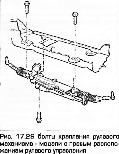
29. Install the mechanism mounting bolt accessible from below and tighten it to the specified torque. Tighten the two upper bolts to the specified torques (fig. 17.29).
30. Secure the hydraulic pipes under the machine and tighten the connecting bolts using new O-rings on both sides of the fittings. Make sure the pipes are positioned correctly and tighten the fitting mounting bolts to the specified torque. Tighten the pipe mounting bolts securely. Remove the clamps from the hoses.
31. Working from inside the vehicle, place the flexible plastic cover on the steering gear shaft and secure it to the engine shield.
32. Attach the steering column joint clamp to the shaft. Insert the clamping bolt, turn it half a turn counterclockwise. Screw on the nut and tighten it "by hand".
33. Remove the wire holding both sections of the steering column together.
34. Unscrew the homemade bolt from the inspection hole in the rack housing, screw in the original plug and tighten it to the specified torque.
35. Tighten the steering column joint clamp bolt to the specified torque.
36. Install the trims under the driver's side dashboard.
37. Install the plastic cover inside the wheel arch, covering the window in the mudguard for the steering rod to pass through. Secure it with clamps and plastic nuts.
38. Install the upper wishbone mounting bracket into the arch, making sure to place all the washers in their places. Screw in the three mounting bolts and tighten them to the specified torque.
39. Attach the lower portion of the suspension strut to the lower control arm as described in paragraph 3. Tighten the mounting bolt and nut to the specified torque.
40. Install the right steering knuckle as described in paragraphs 17...23 paragraph 2 of this chapter. Be careful not to damage the rubber covers.
41. Install the heat shield in front of the steering gear.
42. On models with air conditioning, connect the wiring to the pressure sensor on the rack housing.
43. Install the wheels, lower the vehicle and tighten the wheel bolts to the specified torque.
44. Tighten the hub bolt to the specified torque as described in paragraph 2 of chapter 8, then install the hub cap.
45. Install the battery tray and tighten the mounting bolts securely. Install the battery as described in chapter 5A. Install the cover on the butt at the rear of the engine compartment.
46. Install the air filter and air ducts as described in the relevant section chapters 4.
47. Add brake fluid to the reservoir as described in Weekly checks and bleed the hydraulic system as described in paragraph 19.
48. Finally, have the front wheel alignment checked at the earliest opportunity by contacting your dealer or an appropriate workshop.
(The original article is available on the online resource Audimanual.ru)