
Table of contents: Removal ↓ Installation ↓
Removal
1. Remove the wheel hub cap and loosen the hub bolt slightly while the car is still on the wheels. Loosen the mounting bolts of the corresponding wheel as well.
2. Place chocks under the rear wheels, apply the handbrake, raise the front of the car and install safety stands. Remove the corresponding front wheel. After removing the wheel, tighten one of its mounting bolts into the hub to maintain the position of the brake disc in relation to the hub.
3. Loosen the mounting screws and remove the lower engine cover to gain access to the drive shaft. If necessary, remove the transmission heat shield to improve access to the inner joint.
4. On models with ABS, remove the wheel sensor from the hub as described in chapter 9. Release the sensor wiring from the mounting bracket on the brake caliper.
5. Loosen the pinch bolt and separate the front and rear upper control arm joints from the steering knuckle as described in paragraph 5 of chapter 10. Throw away the nut, a new one is required for installation.
Warning: Do not remove the steering tip from the steering knuckle.
6. Loosen the hub bolt. If you forgot to loosen the bolt while the car was standing on its wheels, screw the two wheel mounting bolts into the hub. Tighten them securely and ask an assistant to press the brake pedal. With the hub locked in this way, you can loosen the bolt. To fix the hub, you can make a tool from two metal strips fastened in the form of a fork, the ends of which are screwed to the hub with wheel bolts.
7. Unscrew the bolts securing the inner joint to the gearbox flange, remove the reinforcing plates (if they are provided). Tie the shaft with wire - do not let it hang down to avoid damaging the joint.
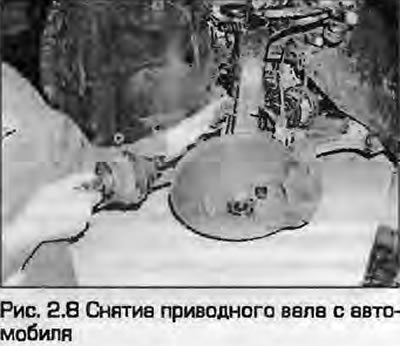
8. Bend the steering knuckle back to disengage the inner joint from the transmission flange. Move the joint to the side and remove the outer joint from the splined connection with the hub. Remove the shaft from under the car (Fig. 2.8). If provided, remove the gasket from the surface of the inner joint and discard it - you will need a new one for installation.
Note: When the drive shafts are removed, do not lower the car onto the wheels - you can damage the hub bearings. If you need to roll the car, insert the old unusable outer joints into the hubs and tighten the hub bolts. You can also install the usable drive shafts: in this case, the inner joints must be tied up so as not to damage them.
Installation
9. Before installing the shaft, inspect the shaft seal on the gearbox. If necessary, replace it on manual gearboxes as described in chapter 7A.
10. Thoroughly clean the splined joint of the outer joint and the hub, as well as the mating surfaces of the inner joint and the flange. Then make sure that the boots are securely fastened.
11. For ball type inner joints, install a new gasket onto the mating surface by pulling back the protective foil and gluing it to the joint.
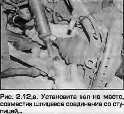
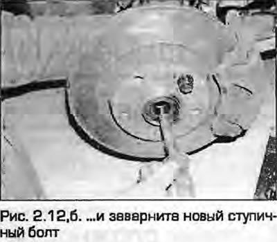
12. Install the shaft in its place, aligning the splined connection with the hub. Install the new hub bolt and tighten it "by hand" (fig. 2.12, a, b).
 |
 |
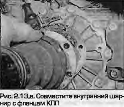
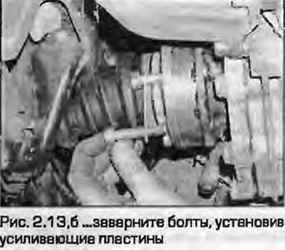
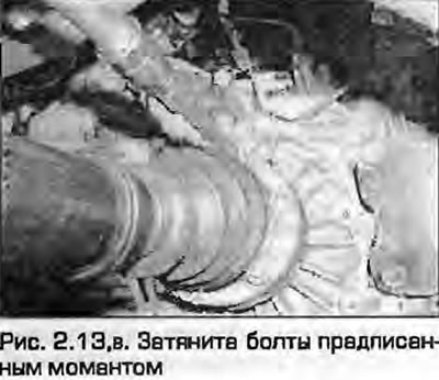
13. Align the inner joint with the gearbox flange, after this tighten the mounting bolts with reinforcing plates (they are provided on ball-type hinges). Carefully tighten all bolts "by hand", then tighten them in a diagonal sequence to the specified torque (fig. 2.13, a-c). If necessary, install the heat shield on the gearbox housing and securely tighten its mounting bolts.
 |
 |
14. Install the front and rear upper control arms onto the steering knuckle and insert the pinch bolt. Install the new mounting nut and tighten it to the specified torque as described in chapter 10.
15. On models with ABS, install the wheel sensor on the hub as described in chapter 9. Secure the sensor wiring to the support.
16. Install the lower protective cover and wheel. Lower the vehicle and tighten the wheel mounting bolts to the specified torque.
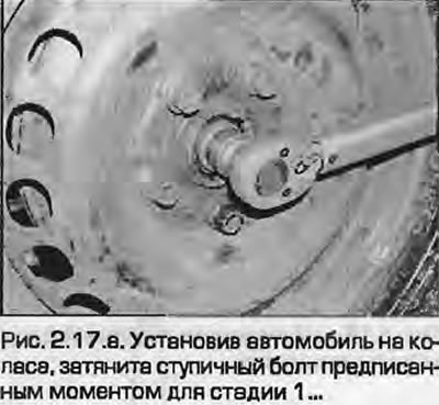
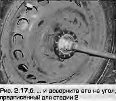
17. After installing the vehicle on the wheels, tighten the hub bolt to the specified torque for stage 1, then turn it to the angle specified for stage 2, using a goniometer (fig. 2.17, a, b). If you do not have a bevel tool, apply angle marks to the hub before tightening to ensure proper alignment.
 |
 |
18. Install the wheel/hub cap.