
Table of contents: Removal ↓ Installation ↓
Removal
49. Apply the handbrake, place chocks under the rear wheels, and loosen the front wheel mounting bolts. Raise the front of the car and install safety supports. Remove both front wheels. When removing the wheels, tighten one wheel mounting bolt into the hubs to prevent the brake discs from shifting.
50. Remove the battery as described in chapter 5A. Loosen the mounting bolts and remove the battery shelf.
51. Turn the steering wheel to the center position and remove the ignition key so that the steering column is locked
Warning: Make sure that the steering wheel and front wheels remain in this position throughout the procedure, otherwise the airbag contact group will move and a malfunction will occur in the system.
52. Remove the storage box under the front panel.
53. Remove the trim panels under the driver's side fascia to access the base of the steering column.
54. Tie the upper and lower sections of the column together with wire. This is necessary so that they do not fall apart when the column is removed from the steering shaft.
Warning: When removing the steering column from the steering gear shaft, do not allow it to separate into sections - the alignment of the internal components will be disrupted.
55. Loosen the nut of the clamp bolt securing the joint to the steering gear shaft. Turn the bolt half a turn and remove it from the clamp.
56. Pull the steering column joint off the steering shaft and set it aside. Remove the plastic trim from the engine shield and pull it into the passenger compartment.
57. Pump out the hydraulic fluid from the power steering reserve tank. If you can't find a suitable hose for this, the fluid will drain itself when you disconnect the hydraulic tubes from the mechanism - then at least put a basin underneath.
58. Clamp the hoses at the power steering reserve reservoir with clamps or clips. This will minimize fluid loss during subsequent operations. Do not puncture the hoses.
59. Unscrew the plastic nut, unhook the latches and remove the part of the mudguard that covers the window in the body for the passage of the steering rod to the steering knuckle.
60. Apply markings to facilitate assembly, unscrew the bolts connecting the tubes to the steering mechanism; be prepared for a liquid spill - place a suitable container underneath. Disconnect both tubes and remove the sealing washers. Throw away the washers - new ones are required for installation. Plug the holes to prevent liquid from leaking out and dirt from getting into the system.
61. Disconnect the steering tips from the steering knuckles - see paragraph 21.
62. Loosen the bolts securing the steering gear to the body.
63. Check again that everything is disconnected and removed from the mechanism, unfasten the plastic collar from the steering gear housing and remove the mechanism, bringing it out through the left arch.
64. If it is known in advance that the rack is damaged, it may need to be replaced. However, the mechanism can be repaired - contact your Audi/VAG dealer for advice.
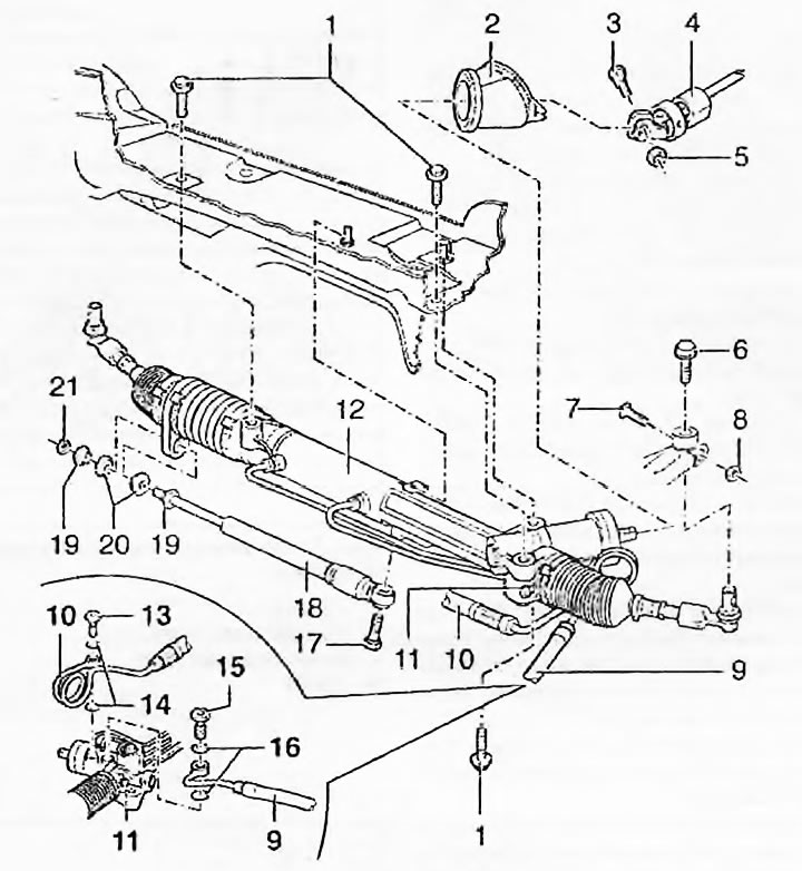
Fig. 17.64. Steering gear components - left-hand models: 1. Bolt; 2. Collar; 3. Eccentric bolt; 4. Steering column; 5. Nut; 6. Bolt; 7. Bolt; 8. Nut; 9. Return pipe; 10. Feeding tube; 11. Inspection hole; 12. Steering mechanism; 13. Hollow bolt; 14. Sealing ring; 15. Hollow bolt; 16. Sealing ring; 17. Bolt; 18. Damper; 19. Bushing; 20. Bushing; 21. Nut
Installation
65. When installing the rack, it is necessary to center it. Unscrew the plug with the internal hexagon from the inspection hole on the side of the mechanism housing. Move the right steering rod by hand so that the hole on the rack is visible in the inspection hole. Take a bolt with the same thread as the plug and sharpen it to a cone. Screw the bolt into the housing so that its cone enters the hole in the rack. Check the fixation of the rack by pulling it by the rods. The rack has taken the middle position (see fig. 17.26).
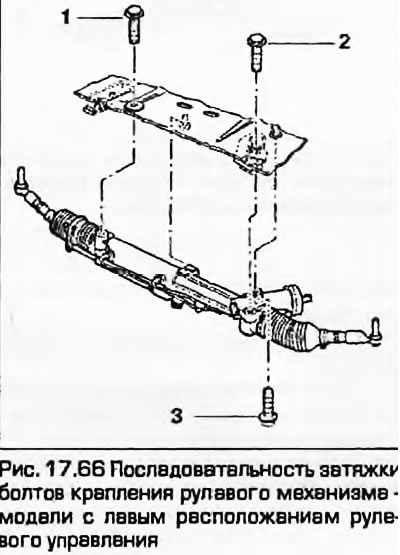
66. Install the mechanism in place, trying not to damage the hoses and wiring, lay them out correctly. Tighten the three rack mounting bolts, tightening them to the prescribed torques in the sequence shown in Fig. 17.66. Unscrew the homemade fixing bolt and tighten the original plug.
67. The rest of the procedure is the reverse of the removal procedure. Please note the following:
- a) The hydraulic pipes are connected after the rack has been secured to the engine shield. Make sure that no dirt gets into the system. Tighten the connection bolts to the specified torques, using new sealing washers.
- b) Tighten all fasteners to the specified torques.
- c) As described in paragraph 21, attach the steering tips.
- d) Add fluid to the hydraulic system as described in "Weekly checks" and pump it up - see paragraph 19.
- d) Finally, have the wheel alignment checked by your dealer or an appropriate workshop.
(Read the original source on the website audimanual.ru)