
Table of contents: Principle of regulation ↓ Determining the value of the… ↓ Selecting the secondary shaft rear… ↓ Checking the adjustment of the… ↓ Calculation of the thickness of the… ↓
Principle of regulation
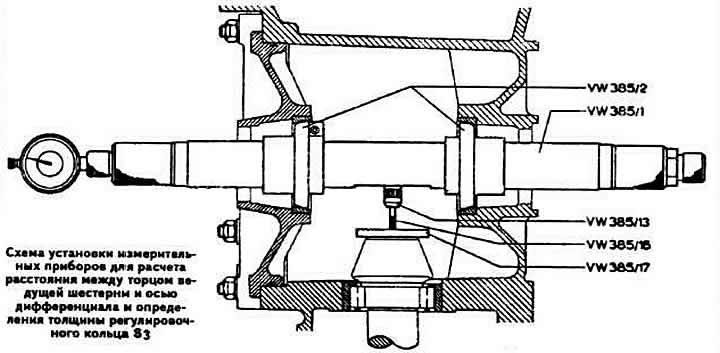
The distance between the differential axis and the end of the drive gear determines the location of the contact patch in the engagement of the main gear gears. When installing the secondary shaft in the gearbox, this distance affects the degree of wear and noise of the main gear gears. Therefore, it must be adjusted with special care using a special tool.
The initial value for adjustment is the calculated value of the distance between the differential axis and the end of the drive gear (constant dimension "Ro", equal to 50.70 mm, see diagram), adjusted by the correction "r", determined during the manufacture of the drive gear. The correction value "r" is indicated in hundredths of a millimeter, always with the "+" sign on the driven gear of the main transmission. For example, if the mark "25" is applied to the driven gear, this means that "r" is equal to 0.25 mm. The adjustment consists of placing the adjusting ring S₃ of the required thickness under the outer ring of the secondary shaft rear bearing to shift the drive gear in the gearbox housing.
Determining the value of the correction "r"
Note: This measurement is taken if the driven gear of the main transmission does not have the correction marking "r" in hundredths of a millimeter from the nominal position of the driving gear, and also if parts that directly affect the position of the driving gear of the main transmission have been replaced (secondary shaft rear double-row tapered roller bearing, gearbox housing or rear cover, 1st gear pinion bearing).
Remove the rear gearbox cover.
Install the VW 381/11 mounting bracket and secure it strictly at a right angle relative to the secondary shaft, tightening two M6x50 bolts by hand.
Tighten the bolts to 200 Ncm using a torque wrench.
The pinion gear, after tightening the bolts, assumes the position it occupied when the rear cover of the gearbox was installed. This operation must be carried out very carefully every time the distance between the end of the pinion gear and the differential axle is adjusted.
Remove the differential.
Install the VW 385 measuring mandrel with the VW 385-30 indicator into the clutch housing with a 2 mm foot preload. Set the arrow to "zero".
Determine the calculated value of the size "r", which represents a deviation from the size "Ro", by the maximum deviation of the indicator arrow (to the point of starting the movement in the opposite direction).
When replacing parts, select the thickness of the adjusting ring to achieve maximum possible accuracy in maintaining the size "r".
Selecting the secondary shaft rear bearing adjusting ring
I. After replacing the parts that determine the position of the main gear drive pinion.
Press the outer ring of the rear double-row tapered roller bearing of the secondary shaft together with the old adjustment ring "S₃" into the gearboxhousing.
Install the selected secondary shaft into the gearbox housing and press in the second inner ring of the secondary shaft rear bearing.
Clamp the gearbox housing in a vice with soft pads and tighten the nut on the rear end of the secondary shaft to a torque of 10.0 kgf·m.
Install a new gasket on the gearbox housing, connect the gearbox housing together with the secondary shaft to the clutch housing and secure them with four bolts.
Measure the value "r" again using the universal measuring mandrel VW 385/1.
If "r₁" is less than "r", then it is necessary to install an adjustment ring of increased thickness. If "r₁" is greater than "r", it is necessary to install an adjustment ring of smaller thickness.
Example.Let's assume that the value of "r" is 0.45 mm, and the value of "r₁" is 0.36 mm. The value of "r₁" is less than "r". Therefore, the thickness of the adjusting ring must be increased by the difference between "r" and "r₁". Using the formula S₃ =S'₃ +(rr₁) we determine the thickness of the adjusting ring installed under the outer ring of the secondary shaft rear bearing, where:
S₃ — thickness of the new adjustment ring;
S'₃ is the thickness of the old adjustment ring, equal to, say, 0.80 mm;
g — calculated value of the correction to the nominal position of the main transmission pinion;
r₁ is the actual value of the correction to the nominal position of the main drive gear.
S₃ =0.80+(0.45-0.36)=0.80+0.09=0.89 mm
II. After replacing the main gear
Note: The following procedure for selecting the secondary shaft rear bearing adjusting ring is only applicable when the final drive has been replaced. If any components that determine the position of the final drive pinion have been replaced, the procedure is as described above.
Press the outer ring of the secondary shaft rear bearing into the rear cover of the gearbox housing without the old adjusting ring "S₃", using the support ring 30-205 and the mandrels 30-505 and VW 412.
Install the secondary shaft into the rear cover of the gearbox housing and press on the inner rear bearing of the secondary shaft.
Turn the secondary shaft several times in both directions.
Clamp the gearbox housing in a vice with soft pads and tighten the nut on the rear end of the secondary shaft to a torque of 10.0 kgf·m.
Install a new gasket on the gearbox housing, connect the gearbox housing together with the secondary shaft to the clutch housing and secure them with four bolts.
Install the VW 381/11 mounting bracket and secure it strictly at a right angle to the secondary shaft, tightening two M8x50 bolts by hand.
Tighten the bolts to 200 Ncm using a torque wrench.
The pinion gear, after tightening the bolts, takes the position it occupied when the rear cover of the gearbox was installed. This operation must be carried out very carefully every time the distance between the end of the pinion gear and the differential axle is adjusted.
Set the movable adjustment ring of the VW 385/1 measuring mandrel to dimension "a" (see photo), equal to 50 mm.
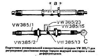
Attach the "C" indicator with a 0-3 mm scale and a 12.3 mm long extension to the measuring mandrel.
Adjust the VW 385/30 gauge to the calculated distance "Ro" between the end of the drive gear and the differential axis equal to 50.70 mm, and install the gauge on the measuring mandrel. Set the indicator arrow to zero with a preliminary tension of the leg of 2 mm.
Using the knurled screw, move the movable adjustment ring back until it stops.
Install the VW 385/17 ring onto the pinion head and insert the universal measuring mandrel into the clutch housing.
Warning: During measurement, the indicator extension leg must be kept in constant contact with the ring to prevent the ring from moving off the pinion head when the leg is retracted.
Install the differential case cover with the pressed-in outer differential bearing and secure it with four bolts.
Pull the second adjusting washer back as far as possible using the movable adjustment ring until the measuring mandrel can be turned only slightly by hand.
Turn the measuring mandrel slightly in both directions so that the indicator leg rests against the ring installed on the head of the drive gear, and the indicator arrow deflects (to the point of starting the movement in the opposite direction). Let the value of "r" measured in this way be 0.15 mm.
Calculate the thickness of the adjustment ring "S₃" using the formula:
S₃=r₁+r,
where:
r₁ — measured value by the maximum deviation of the indicator arrow;
r is the correction value to the nominal position of the main transmission drive gear, marked on the driven gear or measured, as in our case, and equal to 0.45 mm.
Example. "r₁" is equal to 0.15 mm; "r" — 0.45 mm.
S₃ = 0.15 + 0.45 = 0.60 mm.
Since the tolerance limits of the thickness of the adjusting rings are known, in all cases it is possible to accurately select the adjusting ring "S₃" of the calculated thickness.
Checking the adjustment of the distance between the end of the drive gear and the differential axle
Install the secondary shaft, press in the outer ring of the rear bearing, placing the selected adjusting ring "S₃".
Install the universal measuring mandrel and perform a control measurement.
When the adjustment ring is correctly selected, the indicator should show the correction value "r" with a deviation of ±0.04 mm. Read the indicator readings in a counterclockwise direction.
Adjusting the lateral clearance in the engagement of the main gear gears and the preload of the differential box bearings
This adjustment is necessary when replacing the main gear of the gearbox housing, differential box and bearings, as well as when adjusting the distance between the end of the drive gear and the differential axis.
The differential bearings must be installed with a preload of 0.40 mm.
The preliminary tension of the differential bearings and the lateral clearance in the engagement of the main transmission gears are ensured by selecting the thickness of the adjusting rings S₁ and S₂ (see diagram).
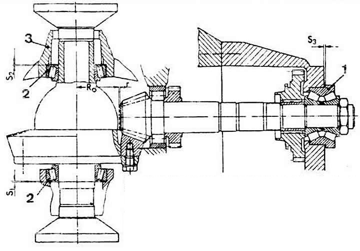
Adjustment and measurement of the distance between the end of the drive gear and the differential axis and the lateral clearance in the engagement of the main gear:
1 - secondary shaft rear roller bearing;
2 - differential bearing;
3 — clutch housing;
R0 — the calculated distance between the end of the drive gear and the differential axis;
r — correction to the calculated distance between the end of the drive gear and the differential axis (applied to driven gears supplied as spare parts);
S₁, S₂ — differential bearing preload adjusting ring;
S₃ — adjusting ring of the distance between the end of the drive gear and the differential axis
Remove the sealing rings, press the outer rings of the differential bearings out of the clutch housing and remove the adjusting rings.
Press in the outer ring of the tapered roller bearing from the side opposite the teeth of the driven gear of the main transmission, with a mounting ring "A" (see diagram) with a thickness of 1.20 mm.
Press the outer ring of the differential bearing until it stops from the side of the driven gear teeth without the adjusting ring.
Install the differential with pressed-on inner bearing rings without the speedometer drive pinion, install the differential cover and tighten the nuts of its mounting bolts crosswise.
Install the differential so that its axis is in the vertical plane (see diagram).
Install the VW 385/17 indicator support frame onto the differential case.
Using the VW 387 device, secure the indicator with a 0-3 mm scale with the VW 322/8 extension, 22 mm long. Mount the indicator leg on the support mandrel with a preliminary tension of 1 mm. Fix the indicator in this position and set it to "zero".
Install the clamping sleeve VW 521/4 with the sleeve VW 521/8 on the differential cover (see diagram).
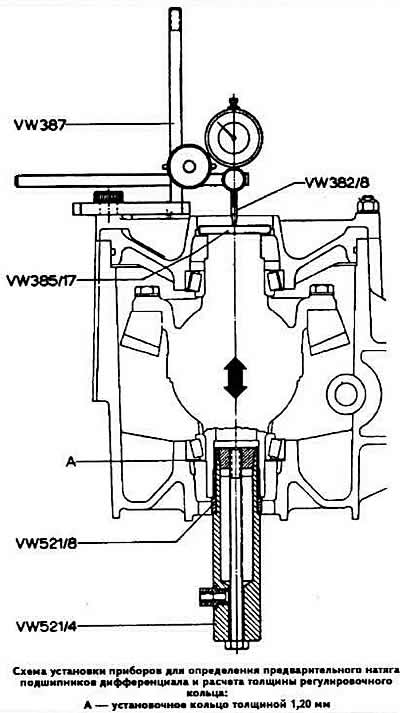
By moving the differential up and down, determine the axial displacement "B" of the differential using the indicator, which, for example, is equal to 0.30 mm.
Warning: To accurately measure the differential axial movement, do not rotate the differential during measurement, thereby eliminating self-alignment of the bearings.
According to formula Sabout=A+B+C calculate the total thickness of the differential box bearing adjusting rings, where:
Sabout — total thickness of adjusting rings "S₁" and "S₂" (see diagram) of differential box bearings;
A - thickness of the mounting ring, equal to 1.20 mm;
B is the value of the differential axial displacement;
C is the value of the preliminary tension of the differential box bearings.
Sabout=1.20+0.30+0.40=1.90 mm.
Using the formula S₁ = B + C, temporarily determine the thickness of the adjusting ring "S₁" of the differential bearing, installed on the side opposite the teeth of the driven gear.
S₁ = 0.30 + 0.40 = 0.70 mm.
Remove the differential cover, press out the outer bearing ring and install the adjusting ring "S₁" with a thickness of 0.70 mm.
Press in the outer race of the differential bearing and install the differential cover.
Install the secondary shaft with the selected "S₃" ring, which determines the distance between the end of the drive gear and the differential axis (the selection method is described above).
Turn the differential several times to allow the bearings to align themselves.
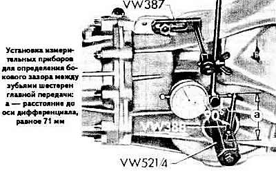
Install devices for measuring the lateral clearance between the teeth of the driving and driven gears when the differential is rotating and when the secondary shaft is stationary; the measurement is taken along the diameter at a distance of 71 mm from the differential axis. The lateral clearance between the teeth of the driving and driven gears should be within 0.10-0.20 mm.
Install the VW 381/11 mounting bracket and secure it strictly at a right angle to the secondary shaft, tightening two M8x50 bolts by hand.
Tighten the bolts to 200 Ncm using a torque wrench.
The pinion gear, after tightening the bolts, assumes the position it occupied when the rear cover of the gearbox was installed. This operation must be carried out very carefully every time the distance between the end of the pinion gear and the differential axle is adjusted.
Turn the driven gear to the stop and set the indicator 8 to the zero position. Return the driven gear by turning it to the stop and measure the lateral clearance between the teeth of the driving and driven gears. Record the indicator readings.
Loosen the differential clamp sleeve lock bolt and the secondary shaft mounting bracket mounting bolts.
Repeat the above operation three times, each time turning the driven gear by 90°.
Warning: If the measured values differ by more than 0.06 mm, the driven gear or main pair is installed incorrectly. Check the correct assembly and replace the main pair if necessary.
Calculate the average value of the lateral clearance between the teeth of the driving and driven gears.
Example. Let's assume that the value of the lateral clearance at the first measurement is 0.45 mm, at the second - 0.47 mm, at the third - 0.46 mm, at the fourth - 0.46 mm, i.e. the average clearance value is (0.45 + 0.47 + 0.46 + 0.46).46)/4 = 0.46 mm.
Calculate the thickness of the adjusting ring "S₂" according to the formula S₂ = (AB) + C, where:
S₂ — thickness of the adjusting ring installed under the outer ring of the differential bearing on the side of the driven gear ring gear;
A - thickness of the mounting ring, equal to 1.20 mm;
B is the value of the average lateral clearance between the teeth of the driving and driven gears;
C — calculated thickness of the ring "SS₂" (constant), equal to 0.15 mm.
Example.In our example, "A" is 1.20 mm, "B" is 0.46 mm, "C" is 0.15 mm.
S₂ =(1.20—0.46)+0.15=0.89 mm.
Calculate the thickness of the adjusting ring "S₁" for the outer ring of the differential bearing, installed on the side of the toothed ring of the driven gear, using the formula S₁ =Sabout-S₂.
Example. In our example "Sabout" equals 1.90 mm, "S₂" — 0.89 mm.
S₁ —1.90-0.89=1.01 mm.
Since the thickness of the adjusting rings is known, in all cases it is possible to select adjusting rings of the calculated thickness with high accuracy.
Measure the thickness of the adjusting rings around the circumference with a micrometer at several points. In addition, make sure that there are no burrs or other defects on the surface of the rings.
Install, observing the techniques described above, adjusting rings of the required thickness "S₁" and "S₂" of the differential box bearings under the outer rings.
Measure the lateral clearance between the teeth of the driving and driven gears at four points around the circumference. The clearance should be within 0.10-0.20 mm.
Warning: Measurement results should not differ from each other by more than 0.05 mm.
If new bearings are installed, check the differential turning torque, which should be 250 N·cm.
Calculation of the thickness of the adjusting rings of the rear bearings of the primary and secondary shafts
Note: This operation must be carried out very carefully, since the thickness of the adjusting washer and sealing gasket affects the position of the main gear pinion. Measurements must be made with the outer bearing rings pressed in as far as they will go.
To select the thickness of the bearing adjusting rings, it is necessary to determine the following dimensions: (see picture):
a — protrusion of the primary shaft ball bearing from the gearbox housing;
b — protrusion of the secondary shaft tapered roller bearing from the gearbox housing;
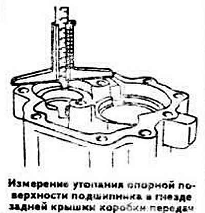
c — recession of the supporting surface of the secondary shaft rear bearing in the rear cover of the gearbox;
d — recession of the supporting surface of the rear bearing of the primary shaft in the rear cover of the gearbox;
s — thickness of the adjusting ring of the secondary shaft rear bearing;
v — thickness of the adjusting ring of the rear bearing of the primary shaft;
e — thickness of the sealing gasket.
Use the depth gauge to determine the dimensions of "a", "b", "c" and "d".
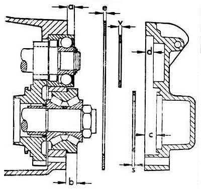
Scheme for selecting adjusting rings when installing the rear bearings of the primary and secondary shafts in the rear gearbox:
a — protrusion of the rear bearing of the primary shaft;
b — protrusion of the secondary shaft rear bearing;
c — recession of the supporting surface of the secondary shaft rear bearing;
d — recession of the supporting surface of the rear bearing of the primary shaft;
e — thickness of the sealing gasket;
v — thickness of the adjusting pin of the rear bearing of the primary shaft;
s — thickness of the adjusting ring of the secondary shaft rear bearing.
The primary shaft bearing of some gearboxes is combined (roller-ball). In this case, a sealing gasket with a thickness of 0.40 mm is installed, and the adjustment of the axial movement of the bearings is carried out by selecting the thickness of the adjusting rings installed under the bearings of the primary and secondary shafts.
On other gearboxes, the required protrusion of the rear bearing of the primary shaft is ensured by installing a sealing gasket with a thickness of 0.30 or 0.40 mm.
The rear bearings of the primary and secondary shafts are installed with a preliminary load of 0.10 mm, ensured by compression of the sealing gasket. On a gearbox with a primary shaft ball bearing, the gasket thickness is selected based on the value of dimension "a". If dimension "a" is 0.20-0.26 mm, a gasket with a thickness of 0.30 mm should be installed. If dimension "a" is in the range of 0.27-0.42 mm, it is necessary to install a gasket with a thickness of 0.40 mm. On a gearbox with a combined primary shaft bearing, the gasket thickness is constant and equal to 0.40 mm.
Calculate the thickness of the adjusting rings using the formulas:
s=c-b+0.3,
v=d-a+0.4.
(The full version is posted on the resource: «AUDIMANUAL.RU»)