Repair Chevrolet Repair Toyota Repair Honda Repair AvtoVAZ Repair Mercedes-Benz Repair BMW Repair Opel
Home  |  Contacts  |  Sitemap  |    
English Русский
Български
Беларускі
Український
Српски
Hrvatski
Română
Polski
Slovenský
Magyar
AudiManual.ru


  • AUDI 80
  • AUDI 100
  • AUDI A3
  • AUDI A4
  • AUDI A6
  • AUDI A8
  • AUDI Q
  • OTHER
  • ARTICLES
C4 (1990-1994) C4 (1990-1994, petrol) C3 (1982-1990) C3 (1982-1990, petrol) C3 (1982-1990, diesel)

Adjusting the distance between the end of the drive gear and the differential axle (Audi 100 C3)

  • Home
  • Audi 100
  • C3 (1982-1990, petrol)
  • Transmission
  • 4 speed gearbox 014
  • Adjusting the distance between the end of the drive gear and the differential axle
            0
Table of contents: Principle of regulation ↓ Determining the value of the… ↓

Principle of regulation


The distance between the differential axis and the end of the drive gear determines the location of the contact patch in the engagement of the main gear gears. When installing the secondary shaft in the gearbox, this distance affects the degree of wear and noise of the main gear gears. Therefore, it must be adjusted with particular care using a special tool.

The initial value for adjustment is the calculated value of the distance between the differential axis and the end face of the drive gear (dimension "Ro", see diagram), adjusted by the correction "r", determined during the manufacture of the drive gear. The adjustment consists of placing the adjusting ring S3 of the required thickness under the outer ring of the secondary shaft rear bearing to shift the drive gear in the gearbox housing.

Diagram of installation of measuring instruments for calculating the distance between the end of…

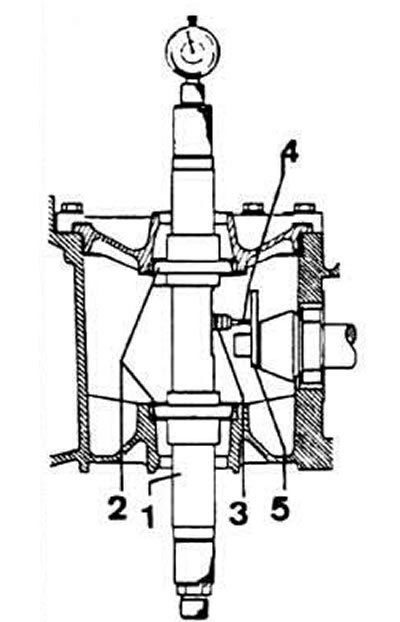
Diagram of installation of measuring instruments for calculating the distance between the end of the drive gear and the differential axis: 1 - measuring mandrel VW 385/1; 2 - measuring mandrel VW 385/2; 3 - indicator rod VW 385/13; 4 - VW 385/16 indicator extension; 5 - support mandrel of the indicator leg VW 385/33


Determining the value of the correction "r"


Note. This measurement is taken if the driven gear of the main transmission does not have the correction marking "g" in hundredths of a millimeter from the nominal position of the driving gear, and also if there has been a replacement of parts that directly affect the position of the driving gear of the main transmission: the rear double-row tapered roller bearing of the secondary shaft, the crankcase or rear cover of the gearbox, the bearing of the 1st gear gear.


Remove the rear gearbox cover.

Install a special adjusting washer VW 381/11 and secure it strictly at a right angle relative to the secondary shaft, tightening two M8x50 bolts by hand.

Tighten the bolts to 20 Nm using a torque wrench.

The pinion gear, after tightening the bolts, takes the position it occupied when the rear cover of the gearbox was installed. This operation must be carried out very carefully every time the distance between the end of the pinion gear and the differential axle is adjusted.

Remove the differential.

Install the VW 385 measuring mandrel into the clutch housing (calibrated to a preload of 2 mm) to "zero" using the VW 385-3G indicator.

Determine the calculated value of the dimension "r", which is the deviation from the dimension "Ro".

When replacing parts, select the thickness of the adjusting ring to achieve the maximum possible accuracy in maintaining the obtained dimension "r".

Adjustment and measurement of the distance between the end of the drive gear and the differential…

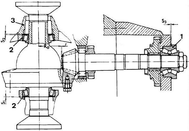
Adjustment and measurement of the distance between the end of the drive gear and the differential axis and the lateral clearance in the engagement of the main transmission gears: 1 - secondary shaft rear tapered roller bearing; 2 - differential bearing; 3 - clutch housing; Ro - calculated distance between the end of the drive gear and the differential axis; g - correction to the calculated distance between the end of the drive gear and the differential axis (applied to driven gears supplied as spare parts); S1, S2 - differential bearing preload adjusting rings; S3 - adjusting ring for the distance between the end of the drive gear and the differential axis


The original text of the material can be found on the website: AUDIMANUAL
The article was checked by auto expert Maxim Rybakov
This article is available at russian, bulgarian, belarusian, ukrainian, serbian, croatian, romanian, polish, slovak, hungarian

Share information:
Previous articles
Audi 100 C3: 4 speed gearbox 014
Next articles

Calculation of the thickness of the adjusting rings of the rear…
Disassembling and assembling the differential
Gearbox assembly
Disassembly and assembly of the secondary shaft
Selecting the secondary shaft rear bearing adjusting ring
Selecting the differential bearing adjusting ring
Adjusting the lateral clearance in the engagement of the main…
Checking the position of the gear shift lever


Similar articles on other Audi car models:
Adjusting the distance between the end of the drive gear and the… Audi 80 B2 (1979-1986)
Adjusting the gas drive Audi A3 Type 8L (1996-2003)
Adjusting the gear shift drive Audi A4 B6 (2000-2006)
Adjusting the gear shift mechanism Audi A6 C5 (1997-2004)
Rear main gear differential Audi A8 D2 (1994-2002)
Adjusting the gear shift mechanism Audi Q5 Type 8R (2008-2017)
Removal and installation the gear shift drive Audi A2 (1999-2005)
Link to this page in different formats


Visitor comments

No comments yet


How much will 35 + 50 =


100(C4, 1990-1994) 
  • General information
  • User manual
  • Power unit
  • Engine repair
  • Ignition system
  • Fuel system (gasoline)
  • Fuel system (diesel)
  • Lubrication system
  • Cooling system
  • Exhaust system
  • Transmission
  • Clutch
  • Car gearbox
  • Drive shafts
  • Chassis
  • Car suspension
  • Steering
  • Wheels and tires
  • Brake system
  • Body
  • Ventilation and heating
  • Body repair
  • Electrical equipment
  • Power devices
  • Lighting and appliances
  • Electrical circuits
 
100(C4, 1990-1994, petrol) 
  • General information
  • Operation and maintenance
  • Power unit
  • Engine repair
  • Exhaust system
  • Cooling system
  • Supply system
  • Air filter
  • Mono-Motronic injection system
  • Digifant injection system
  • KE-III-Jetronic and KE-Motronic
  • MPI and MPFI injection system
  • Transmission
  • Clutch
  • Car gearbox
  • Chassis
  • Suspension and steering
  • Brake system
  • Wheels and tires
  • Body
  • Exterior
  • Interior
  • Electrical equipment
  • Fuses and relays
  • Power devices
  • Ignition system
  • Lighting and signaling
  • Equipment and devices
  • Electrical circuits
 
100(C3, 1982-1990) 
  • General information
  • User manual
  • Maintenance
  • Specifications
  • Power unit
  • Engines 4-cylinder
  • Engines 5-cylinder
  • Diesel engine
  • Cooling system
  • Power system (carburetor)
  • Power system (injector)
  • Fuel system (diesel)
  • Transistor ignition system
  • Electronic ignition system
  • Transmission
  • Clutch
  • 4 speed gearbox 014
  • 5 speed gearbox 013 and 093
  • 5 speed gearbox 016 and 012
  • Shift mechanism KP 016
  • Automatic transmission
  • Front wheel drive
  • Chassis
  • Front suspension
  • Rear suspension
  • Steering
  • Brake system
  • Body
  • Body elements
  • Electrical equipment
  • Lighting and appliances
  • Power devices
  • Electrical circuits
 
100(C3, 1982-1990, petrol) 
  • General information
  • Maintenance and operation
  • 4 cylinder engine
  • Engine repair
  • Cooling and lubrication system
  • Supply system
  • Ignition system
  • 5 cylinder engine
  • Engine repair
  • Cooling and lubrication system
  • Supply system
  • Ignition system
  • Transmission
  • Clutch and drive shafts
  • 4 speed gearbox 014
  • 5 speed gearbox 013 and 093
  • 5 speed gearbox 016 and 012
  • Automatic gearbox
  • Chassis
  • Steering
  • Front suspension
  • Rear suspension
  • Brake system
  • Body
  • Body elements
  • Doors, locks and windows
  • Body repair
  • Electrical equipment
  • Equipment and devices
  • Power devices
  • Electrical circuits
 
100(C3, 1982-1990, diesel) 
  • General information
  • User manual
  • Maintenance
  • Troubleshooting
  • Power unit
  • Engine in a car
  • Engine removed
  • Cooling system
  • Fuel system
  • Exhaust system
  • Starting and charging
  • Preheating
  • Transmission
  • Clutch
  • Mechanical gearbox
  • Automatic gearbox
  • Drive shafts
  • Chassis
  • Brake system
  • Suspension
  • Steering
  • Body
  • Exterior
  • Interior
  • Electrical equipment
  • Equipment and devices
  • Electrical circuits
 
AudiManual.ru © 2017-2026 · Mobile version · Feedback · Sitemap: EN BG BY UA RS HR RO PL SK HU · Site search · News and articles
80 B2 · 80 B3 petrol · 80 B3 · 80 B4 · 100 C3 diesel · 100 C3 petrol · 100 C3 · 100 C4 petrol · 100 C4 · A3 Type 8L · A4 B5 petrol · A4 B5 · A4 B6 petrol · A4 B6 · A4 B7 · A4 B8 · A6 C4 · A6 C5 · A6 C5 Allroad · A8 D2 · Q5 Type 8R · Q7 Typ 4L · Audi A2 ·
This site uses cookies 🍪. Click the button to accept this fact.