
Note: When pressing, make sure that the fork of the 1st and 2nd gears moves freely; if necessary, release it from jamming with light blows of a mallet. At the same time, make sure that the locks remain in place.
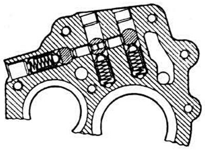
The position of the shift fork rod locks is given below
Install fork I and II on the stem.
gear leash and insert the spring pin.
Install the reverse intermediate gear onto the axle and press the axle in place.
Install the primary shaft into the gearbox housing.
Extend the 3rd and 4th gear shift fork rod so that you can insert the 3rd and 4th gear fork into the cylindrical groove of the synchronizer sliding sleeve. Bring the fork rod to the neutral position and secure the fork to the rod with a spring pin, while holding the rod with a hammer so as not to damage the hole in the crankcase cover.
Install a new gasket and connect the gearbox housing to the clutch housing.
Press in the dowel pins and tighten the gearbox housing mounting bolts to a torque of 2.5 kgf·m.
Install the primary shaft mounting cross member on the clutch housing.
Press the primary shaft ball bearing into the clutch housing socket with the closed part of the separator facing the housing. Install the thrust washer and retaining ring on the ball bearing.
Remove the cross member.
Engage 1st gear and reverse, tighten the nut at the end of the secondary shaft to a torque of 10 kgf·m and lock it.
Set the fork rods to neutral position.
Carefully pull the 3rd and 4th gear shift fork rod towards the 3rd gear pinion until the lock, previously lubricated with a thin layer of grease, can be put back in place. Return the fork rod to the neutral position.
Warning. Move the fork rod only the required distance to avoid the synchronizer crackers falling out, since in this case the fork will not be set to the neutral position. If the crackers fall out, you will have to disassemble the gearbox again, insert the crackers into the grooves of the synchronizer hub (this is possible only in a strictly defined position of the synchronizer locking ring) and slide the sliding sleeve over it.
Select the correct thickness of the adjusting rings to ensure proper installation of the rear bearings of the primary and secondary shafts.
Install the parts into the rear gearbox cover:
- install the spring on the gear selection rod, while the spring leg should rest against the lever on the gear selection rod;
- install the adjusting ring of the secondary shaft rear bearing into the groove of the gearbox cover.
- screw two threaded studs into the gearbox housing cover to center the rear gearbox cover,
- set the fork rods to neutral position and install a gasket of the required thickness;
- insert the gear selector rod leash into the fork rod cutouts.
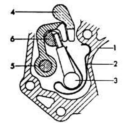
Section of the rear cover of the gearbox: 1 - back cover; 2 - figured spring; 3 - gear selection lever; 4 - reverse gear fork rod; 5 - rod for shifting fork of 1st and 2nd gears; 6 - fork rod for shifting III and IV gears
Slide the rear cover onto the mounting studs in the gearbox housing, move the rear cover to the right and tighten its mounting bolts to 2.5 kgf·m.
[The original article is available on the online resource: AudiManual.ru]