Repair Chevrolet Repair Toyota Repair Honda Repair AvtoVAZ Repair Mercedes-Benz Repair BMW Repair Opel
Home  |  Contacts  |  Sitemap  |    
English Русский
Български
Беларускі
Український
Српски
Hrvatski
Română
Polski
Slovenský
Magyar
AudiManual.ru


  • AUDI 80
  • AUDI 100
  • AUDI A3
  • AUDI A4
  • AUDI A6
  • AUDI A8
  • AUDI Q
  • OTHER
  • ARTICLES
C4 (1990-1994) C4 (1990-1994, petrol) C3 (1982-1990) C3 (1982-1990, petrol) C3 (1982-1990, diesel)

Disassembly and assembly of the primary shaft (Audi 100 C3)

  • Home
  • Audi 100
  • C3 (1982-1990, petrol)
  • Transmission
  • 4 speed gearbox 014
  • Disassembly and assembly of the primary shaft
            0
Table of contents: Disassembly ↓ Assembly ↓

Disassembly


Remove the retaining ring using pliers.

Remove the thrust washer of the fourth gear pinion, the needle bearing and the fourth gear pinion from the shaft.

Remove the 4th gear synchronizer locking ring, then the synchronizer retaining ring.

Press the sliding sleeve with the synchronizer locking ring and the third gear pinion on a press. Remove the third gear pinion needle bearing

Assembly


Install the needle bearing and 3rd gear gear on the shaft.

Check the wear of the synchronizer locking rings, for which press the synchronizer locking rings against the gear synchronizer cones and use a feeler gauge to measure the axial clearance between the end of the locking ring and the end of the gear synchronizer ring, which should be at least 0.5 mm (see picture). If the gap is smaller, replace the synchronizer locking rings.

The arrow shows the recess for the correct connection of the hub with the sliding synchronizer…

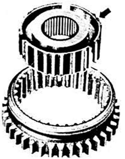
The arrow shows the recess for the correct connection of the hub with the sliding synchronizer clutch, which for the hub of the synchronizer clutch of the 1st and 2nd gears should be directed towards the gear of the 1st gear, and for the hub of the synchronizer clutch of the 3rd and 4th gears - towards the gear of the 4th gear


Install the 3rd gear synchronizer locking ring.

Connect the sliding coupling to the synchronizer hub of the III and IV gears, directing the internal splines of the hub with the beveled edge towards the IV gear pinion (see photo). After installing the three synchronizer crackers, install the springs, placing their connectors at 120°, while the curved ends of the springs must be inserted into the cracker recesses.

Press the synchronizer onto the input shaft by turning the synchronizer locking ring

III gear so that the projections of the ring enter the grooves of the sliding clutch hub, and the beveled edge of the internal splines of the hub is directed towards the III gear gear.

Install the 4th gear synchronizer locking ring and secure it with the retaining ring.

Press the 4th gear pinion with the needle bearing onto the shaft.

Move the 3rd gear pinion and synchronizer until they stop against the retaining ring.

Measure the axial clearance of the fourth gear pinion with a set of feeler gauges (see photo), which should be in the range of 0.10-0.40 mm. Select the appropriate thrust washer to obtain the smallest clearance.

Install the retaining ring.
The article was checked by auto expert Maxim Rybakov
This article is available at russian, bulgarian, belarusian, ukrainian, serbian, croatian, romanian, polish, slovak, hungarian

Share information:
Previous articles
Audi 100 C3: 4 speed gearbox 014
Next articles

Disassembling the gearbox
Removal and installation the gearbox
Four-speed gearbox parts
Tightening torques for main threaded connections
Disassembly and assembly of the secondary shaft
Gearbox assembly
Disassembling and assembling the differential
Calculation of the thickness of the adjusting rings of the rear…


Similar articles on other Audi car models:
Disassembly and assembly of the primary shaft Audi 80 B2 (1979-1986)
Clutch and Drive Shaft Specifications Audi A3 Type 8L (1996-2003)
Cylinder head — disassembly, cleaning, inspection and assembly Audi A4 B5 (1994-2001)
Disassembly and assembly of the drive shaft Audi A6 C5 (1997-2004)
Disassembly and assembly of the shock absorber strut Audi A8 D2 (1994-2002)
Disassembly and assembly of the engine Audi Q5 Type 8R (2008-2017)
Disassembly and assembly of the gearshift mechanism drive Audi A2 (1999-2005)
Link to this page in different formats


Visitor comments

No comments yet


How much will 20 + 50 =


100(C4, 1990-1994) 
  • General information
  • User manual
  • Power unit
  • Engine repair
  • Ignition system
  • Fuel system (gasoline)
  • Fuel system (diesel)
  • Lubrication system
  • Cooling system
  • Exhaust system
  • Transmission
  • Clutch
  • Car gearbox
  • Drive shafts
  • Chassis
  • Car suspension
  • Steering
  • Wheels and tires
  • Brake system
  • Body
  • Ventilation and heating
  • Body repair
  • Electrical equipment
  • Power devices
  • Lighting and appliances
  • Electrical circuits
 
100(C4, 1990-1994, petrol) 
  • General information
  • Operation and maintenance
  • Power unit
  • Engine repair
  • Exhaust system
  • Cooling system
  • Supply system
  • Air filter
  • Mono-Motronic injection system
  • Digifant injection system
  • KE-III-Jetronic and KE-Motronic
  • MPI and MPFI injection system
  • Transmission
  • Clutch
  • Car gearbox
  • Chassis
  • Suspension and steering
  • Brake system
  • Wheels and tires
  • Body
  • Exterior
  • Interior
  • Electrical equipment
  • Fuses and relays
  • Power devices
  • Ignition system
  • Lighting and signaling
  • Equipment and devices
  • Electrical circuits
 
100(C3, 1982-1990) 
  • General information
  • User manual
  • Maintenance
  • Specifications
  • Power unit
  • Engines 4-cylinder
  • Engines 5-cylinder
  • Diesel engine
  • Cooling system
  • Power system (carburetor)
  • Power system (injector)
  • Fuel system (diesel)
  • Transistor ignition system
  • Electronic ignition system
  • Transmission
  • Clutch
  • 4 speed gearbox 014
  • 5 speed gearbox 013 and 093
  • 5 speed gearbox 016 and 012
  • Shift mechanism KP 016
  • Automatic transmission
  • Front wheel drive
  • Chassis
  • Front suspension
  • Rear suspension
  • Steering
  • Brake system
  • Body
  • Body elements
  • Electrical equipment
  • Lighting and appliances
  • Power devices
  • Electrical circuits
 
100(C3, 1982-1990, petrol) 
  • General information
  • Maintenance and operation
  • 4 cylinder engine
  • Engine repair
  • Cooling and lubrication system
  • Supply system
  • Ignition system
  • 5 cylinder engine
  • Engine repair
  • Cooling and lubrication system
  • Supply system
  • Ignition system
  • Transmission
  • Clutch and drive shafts
  • 4 speed gearbox 014
  • 5 speed gearbox 013 and 093
  • 5 speed gearbox 016 and 012
  • Automatic gearbox
  • Chassis
  • Steering
  • Front suspension
  • Rear suspension
  • Brake system
  • Body
  • Body elements
  • Doors, locks and windows
  • Body repair
  • Electrical equipment
  • Equipment and devices
  • Power devices
  • Electrical circuits
 
100(C3, 1982-1990, diesel) 
  • General information
  • User manual
  • Maintenance
  • Troubleshooting
  • Power unit
  • Engine in a car
  • Engine removed
  • Cooling system
  • Fuel system
  • Exhaust system
  • Starting and charging
  • Preheating
  • Transmission
  • Clutch
  • Mechanical gearbox
  • Automatic gearbox
  • Drive shafts
  • Chassis
  • Brake system
  • Suspension
  • Steering
  • Body
  • Exterior
  • Interior
  • Electrical equipment
  • Equipment and devices
  • Electrical circuits
 
AudiManual.ru © 2017-2026 · Mobile version · Feedback · Sitemap: EN BG BY UA RS HR RO PL SK HU · Site search · News and articles
80 B2 · 80 B3 petrol · 80 B3 · 80 B4 · 100 C3 diesel · 100 C3 petrol · 100 C3 · 100 C4 petrol · 100 C4 · A3 Type 8L · A4 B5 petrol · A4 B5 · A4 B6 petrol · A4 B6 · A4 B7 · A4 B8 · A6 C4 · A6 C5 · A6 C5 Allroad · A8 D2 · Q5 Type 8R · Q7 Typ 4L · Audi A2 ·
This site uses cookies 🍪. Click the button to accept this fact.