
Table of contents: Removal and installation levers ↓ Removal and installation the… ↓
Note: Checking the condition and replacing the windshield wiper blades, as well as adjusting the washer fluid nozzles and the parking position of the wiper blades are described in Section 7 Chapter 1. A description of the removal and installation of the steering column switches is given in Section 8.
1. The installation details of the windshield wipers are shown in the illustration.
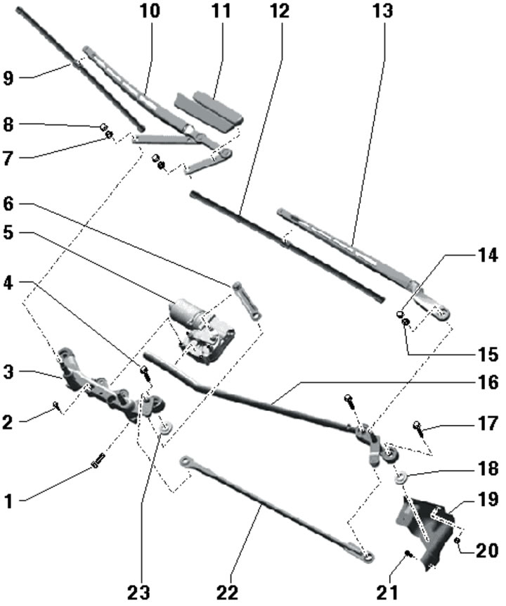
9.1. Windshield wiper installation details:
1, 4, 17, 21 - Bolt, 8 Nm;
2 - Electric motor bolt, 11 Nm; don't weaken;
3 - Right windshield wiper frame, cannot be replaced separately;
5 - Electric motor with control unit;
6, 22 - Connecting rod;
7, 15 - Nut, 35 Nm;
8, 14 - Cap;
9/10 - Right air cleaner brush/lever;
11 - Lever cover 10;
12/13 - Left air cleaner brush/lever;
16 - Left windshield wiper frame, not replaceable separately;
18, 23 - Glued rubber bushing;
19 - Frame support 16;
20 - Nut, 8 Nm.
Removal and installation levers
2. Remove the nut caps from the control arms.
3. To remove the left lever, loosen the nut (3 in the illustration) and remove the lever.
9.3. Lever mounting nuts.
4. If you remove the lever (1 in the illustration) if you can't do it by hand, use the T10369/1 puller, which rests against the axle.
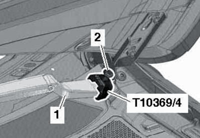
9.4. Removing the left lever.
5. To remove the right lever, loosen the nuts a few turns (1 and 6 in the illustration), install the T10369/1 puller on the lever (4), place the support (5) on the shaft and rotate the bolt (3) until the lever is separated from the axis.
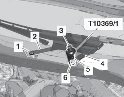
9.5. Removing the right lever.
Then remove the device, completely loosen the nuts and remove the lever.
6. Installation is carried out in reverse order. Adjust the parking position of the levers (see Section 7 of Chapter 1).
Removal and installation the windshield wiper mechanism
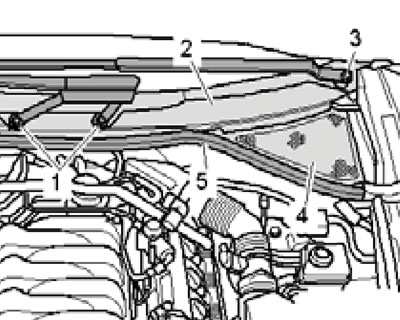
7. Remove both levers (see subsection above), compaction (5 in the illustration) and gutter covers (4 and 2) as described in Section 19 Chapter 1.
8. Remove the bolts (arrows in the illustration), turning the connecting rod if necessary.
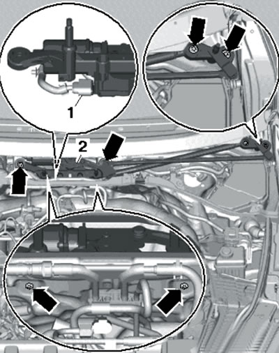
9.8. Removing the electric motor with the control unit.
Remove the entire wiper frame (2) and disconnect the connector (1).
9. Before installation, make sure that all rubber bushings (2 in the illustration) correctly seated in the supports (1).
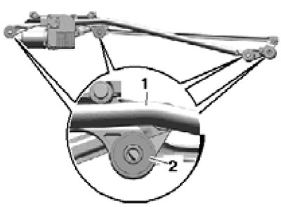
9.9. Rubber bushings.
10. Installation is carried out in reverse order. Tighten the fasteners in the following order: first tighten all fasteners by hand, then tighten the bolts in sequence (1-4 in the illustration), and then tighten the bolts (arrows).
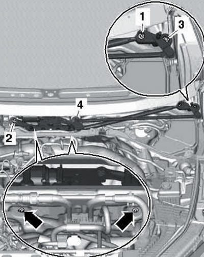
9.10. Fastener tightening sequence.
If the electric motor with the control unit has been replaced, perform the corresponding function in the diagnostic tool menu.
The original article is available on the online resource: Audimanual.ru