
Table of contents: Central armrest ↓ Center console ↓
Central armrest
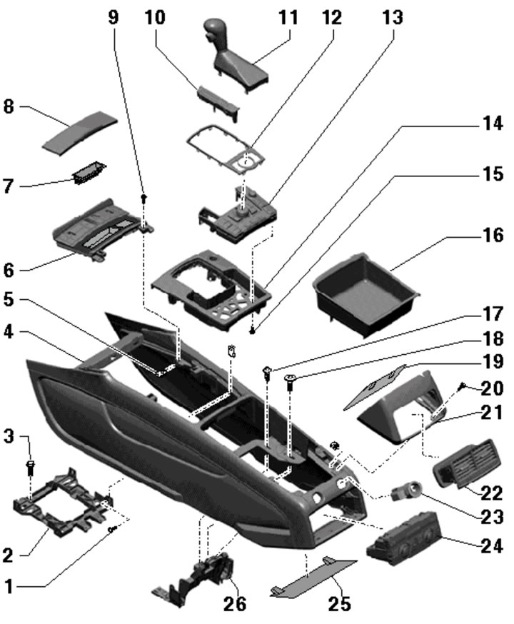
1. The details of fastening and assembly of the central armrest are shown in the illustration.
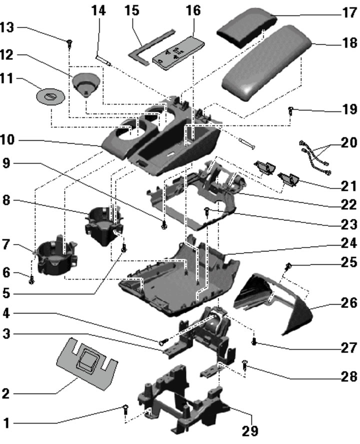
13.1. Central armrest fastening and assembly details:
1 - Bolt, 8 Nm;
2.26 - Bracket cover 3;
3 - Armrest support bracket (upper part);
4 - Bolt, subject to replacement, 4 Nm;
5, 6 - Bolt, 1.2 Nm;
7, 8 - Cup holder;
9, 13, 19 - Bolt, 0.9 Nm;
10 - Glove box, fixed on overlay 24;
11, 12 - Cup holder lining;
14 - Loop axis;
15 - Glove box lining;
16 - Phone/wireless module holder;
17/18 - Right/left armrest cushion;
20 - Telephone/Wireless Module Wiring Harness;
21 - Overlay;
22 - Armrest support;
23 - Bolt, 1 Nm;
24 - Lower armrest pad, fixed in box 10;
25 - Bolt, 2 Nm;
27 - Bolt, 4 Nm;
28 - Bolt, 7.5 Nm;
29 - Armrest support bracket (lower part).
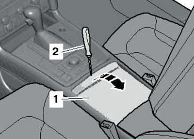
2. Fold the center armrest up and remove the front trim (1 in the illustration), by prying it off with a screwdriver.
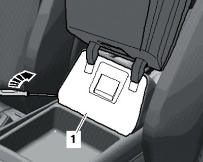
13.2. Removing the front trim.
3. Unscrew the bolt (see illustration) and lower the armrest.
13.3. Front armrest bolt.
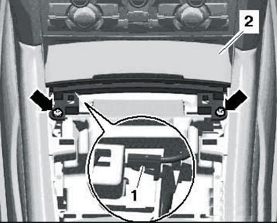
4. Remove the air deflectors on the back of the armrest (see Chapter 3), unscrew the bolts (1 in the illustration) and remove the cover (2) of the armrest support bracket.
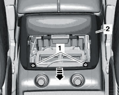
13.4. Fastening the rear armrest trim.
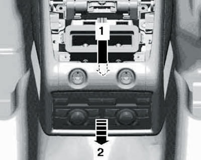
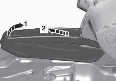
5. Unhook the air duct from below (1 in the illustration) and remove it in the direction of the arrow (2).
13.5. Removing the air duct.
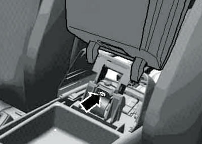
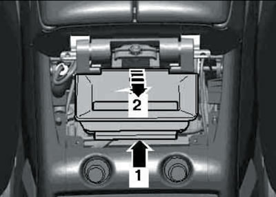
6. Through the opening (1 in the illustration) push back (2) the climate control unit or storage compartment.
13.6. Removing the rear climate control unit.
Do not disconnect the electrical wiring from the control unit.
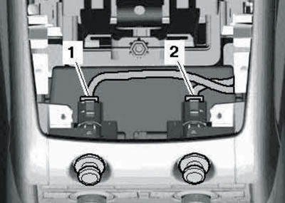
7. Pull out the connectors (1 and 2 in the illustration) and disconnect them.
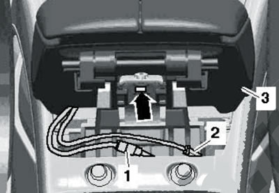
13.7. Rear armrest bolt.
Unscrew the bolt (arrow) and remove the central armrest (3).
8. Installation is carried out in reverse order.
Center console
9. The installation details of the center console are shown in the illustration.
13.9. Center console installation details:
1, 3, 9, 20 - Bolt, 2.0 Nm;
2 - Center console bracket;
4 - Center console;
5 - Embedded nut;
6 - Front ashtray/storage compartment;
7 - Front ashtray insert;
8 - Front ashtray cover;
10 - Selector lever position indicator;
11 - AT mode selector lever;
12 - Frame-cover;
13 - Multimedia control unit "E380";
14 - Block 13 support frame;
15 - Bolt, 0.85 Nm;
16 - Storage compartment/compartment for display control unit "J523";
17 - Bolt, 4 Nm;
18 - Bolt, 8 Nm;
19, 21 - Armrest support bracket cover;
22 - Air vent in the center console;
23 - Cigarette lighter/12V socket;
24 - Rear climate control unit/storage compartment;
25 - Overlay;
26 - Lower support bracket of the central armrest.
10. Remove the center armrest (see subsection above).
11. Disconnect the connectors (1 and 2 in the illustration).
13.11. Socket connectors.
12. If present, remove the CD changer with its support frame. Use a screwdriver to pry up and remove the storage compartment (see illustration).
13.12. Removing the storage compartment of the center console.
13. Remove the front ashtray/front storage compartment. To do this, remove the selector lever position indicator (see Chapter 6), through the opening for the selector lever boot, press out the frame of the multimedia control unit, unscrew the bolts (arrows in the illustration), pull the ashtray (2) back and disconnect the connector (1).
13.13. Removing the front ashtray.
14. Disconnect the connector (1 in illustration 5.18 Chapter 6) and remove the insulation (2) of the selector lever assembly.
15. Remove the bolts (arrows and 1-3 in Illustration 5.19 of Chapter 6).
16. Lift the center console through the support bracket (1 in the illustration) and separate the console from the supports in the instrument panel (2).
13.16. Removing the center console.
Remove the console towards the rear.
17. Installation is carried out in reverse order.