
Table of contents: Pads under the steering column ↓ End caps, glove box and cap… ↓ Front instrument panel trim ↓ Dashboard ↓
Pads under the steering column
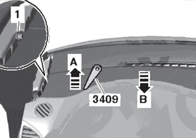
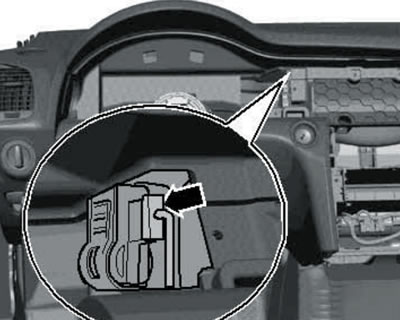
1. Remove the bolts (2 and 3 in the illustration), grasp the top edge of the overlay and pull it down slightly (A).
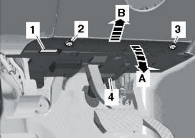
14.1. Removing the lower trim under the steering column.
Release the diagnostic connector (1), disconnect the light connector (4), and remove the trim panel in the direction of arrow (B). If necessary, after removing the lower trim panel, you can remove the upper trim panel as described below.
2. Install wedge #3409 between the instrument panel and the trim as shown in the illustration.
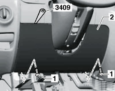
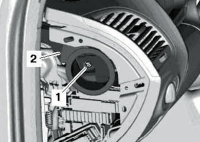
14.2. Removing the upper cover under the steering column.
3. Carefully unhook the hooks (2 in the illustration) cover (1) and pull it out of the instrument panel hooks (3) in the direction of the arrow.
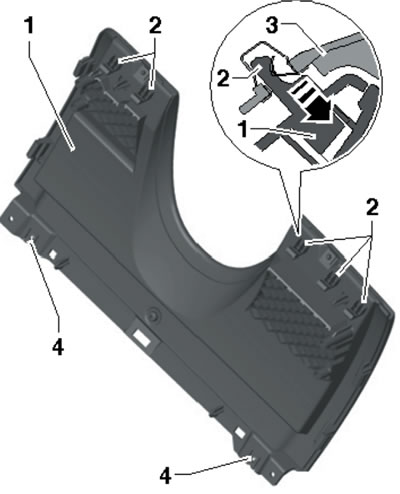
14.3. Upper trim fasteners under the steering column.
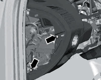
4. Remove the bolts (1 in illustration 14.2) and remove the top cover (2).
5. Installation is carried out in reverse order. Before installation, make sure that the fasteners are present and intact (1 in the illustration).
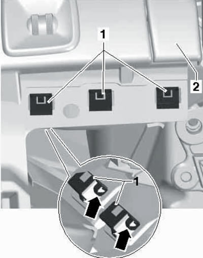
14.5. Clamps in the instrument panel.
End caps, glove box and cap underneath
6. To remove the left or right end trim of the instrument panel, simply pry it off with a screwdriver (see illustration).
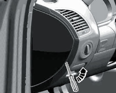
14.6. Removing the left end panel of the instrument panel.
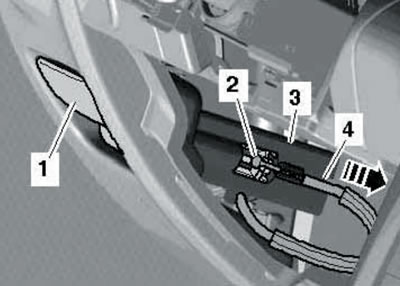
7. To remove the trim under the glove compartment, use wedge No. 3409 to unhook it from the instrument panel (arrows in the illustration) and disconnect the lamp connector (1).
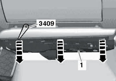
14.7. Removing the cover under the glove compartment.
8. To remove the glove compartment, open it, unscrew the bolts shown in the illustration and disconnect the electrical wiring connectors.
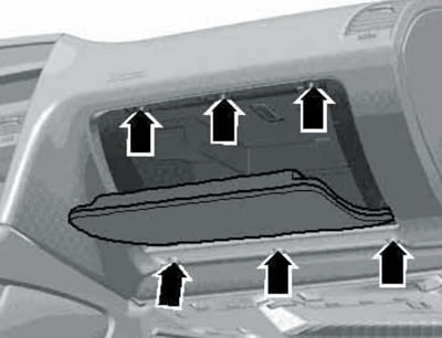
14.8. Fastening of the glove box.
Front instrument panel trim
9. Remove the solar radiation sensor (see Chapter 3) and unscrew the central bolt of the front trim (see illustration).
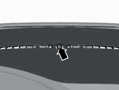
14.9. Front lining bolt.
10. Remove the A-pillar trim and remove the clips (1 in the illustration) on each side, pry up the trim with wedge No. 3409 (A) and separate it from the instrument panel in the rear direction (B).
14.10. Side retainer of the lining and its removal.
If present, disconnect the speaker connector.
Dashboard
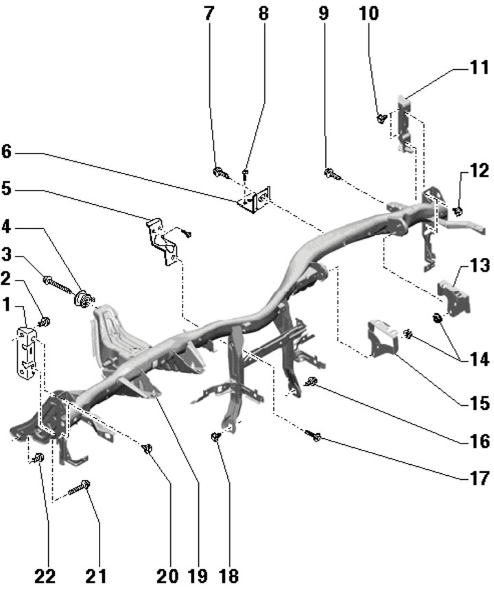
11. The details of the instrument panel installation are shown in the illustration.
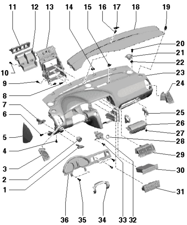
14.11. Instrument panel installation details:
1 - Parking brake release handle;
2 - Outdoor lighting switch;
3 - Left deflector;
4, 6, 8, 16, 33, 35 - Bolt, 1.4 Nm;
5 - Left end plate;
7 - Handle guide 1;
9, 10 - Bolt, 0.6 Nm;
11 - Central upper air duct;
12 - Central air duct;
13 - Mounting frame;
14, 15 - Retainer;
17 - Solar radiation sensor;
18 - Front trim;
19 - Expansion pin;
20 - Bolt, 1.8 Nm;
21 - Speaker;
22 - Embedded nut;
23 - Instrument panel;
24 - Right deflector;
25 - Module bracket 26;
26 - Front passenger airbag module;
27 - Nut, subject to replacement, 7 Nm;
28 - Switch cover 32;
29 - Central deflector;
30 - CD changer;
31 - Climate control unit;
32 - Switch "Engine start/stop";
34 - Overlay;
36 - Instrument cluster.
12. Fully lower and extend the steering column, and move the front seats fully rearward and set their backrests at a 45° angle.
13. Set the selector lever to the "S" position, unlock the glove compartment, turn on the ignition and disconnect the electrical wiring from the battery (see Chapter 5).
14. Remove the steering wheel (see Chapter 9).
15. Remove the center console (see Section 13).
16. Remove the left end trim of the instrument panel (see paragraph 6). Remove the bolt (1 in the illustration) and remove the air duct (2).
14.16. Air duct mounting bolt.
17. Remove the light switch (see Chapter 11) and both pads under the steering column (see paragraphs 1-4).
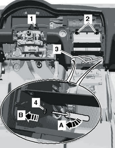
18. Pull out the cable (4 in the illustration) release the parking brake from the bracket (3) in the direction of the arrow.
14.18. Removing the parking brake release handle.
Press the housing (2) out of the handle (1), remove the handle and move the cable to the side.
19. Remove the steering column switches (see Chapter 11).
20. Remove the central air vents, CD changer and climate control unit (see Chapter 3).
21. Remove the instrument cluster and switch "Engine start/stop" (see Chapter 11).
22. If present, disconnect the windshield air supply activator connector (see illustration).
14.22. Activator connector V213.
23. Remove the right end trim of the instrument panel, the glove compartment and the trim underneath it (see the relevant subsection above).
24. Remove the front passenger airbag module and its brackets (see Section 11).
25. Remove the front instrument panel trim (see subsection above) and remove the speakers from the dashboard.
26. Unscrew the instrument panel mounting bolts on the left and right (see illustration).
14.26. Instrument panel side bolts.
If present, disconnect the instrument panel vent connectors.
27. Remove the bolts (1 and 2 in the illustration) and press the electrical wiring connector (3) out of the mounting frame.
14.27. Instrument panel beam fastening details:
1 - Left bracket, mark the position on the A-pillar before removing;
2, 3, 10, 12, 16, 18, 20, 22 - Bolt, 23 Nm;
4 - Compressive element;
5, 6 - Holder of the climate control system housing;
7, 9, 17 - Bolt, 10 Nm;
8 - Bolt, 1.5 Nm;
11 - Right bracket, mark position on A-pillar before removing;
13 - Right bracket of the front passenger airbag module;
14 - Nut, subject to replacement, 7 Nm;
15 - Left bracket of the front passenger airbag module;
19 - Instrument panel beam;
21 - Self-locking bolt, subject to replacement, 23 Nm.
Loosen the bolt (4) on the left and right mounting frame, lift the tab (A) with a screwdriver, and separate the instrument panel from the center pipe in a rearward direction (B). With the help of an assistant, remove the instrument panel from the passenger compartment.
28. Installation is carried out in reverse order. When installing, push the latches in gently while applying pressure (1 in the illustration) instrument panel (3) into the openings on the lower side of the windshield frame (2).
14.28. Central bolts of the instrument panel.