
Table of contents: Tachometer ↓ Digital watch with date indication ↓ Setting the time ↓ Setting the date ↓ Engine oil temperature gauge ↓ Coolant temperature ↓ Operating temperature ↓ Fuel gauge ↓ Speedometer ↓ Information on maintenance periods ↓ Voltmeter ↓ Self-diagnosis system ↓
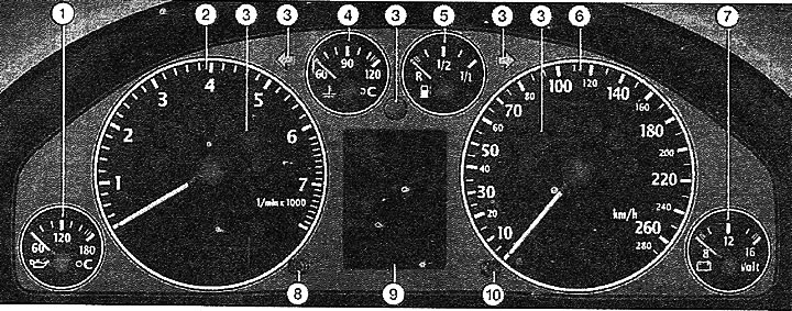
1 - engine oil temperature gauge
2 - tachometer
3 - signal lights
4 - coolant temperature indicator
5 - fuel reserve indicator
6 - speedometer with total mileage counter. The speedometer has a display that shows the daily mileage, as well as messages about vehicle maintenance
7 - voltmeter
8 - Clock setting button/malfunction diagnostic system button/total mileage counter indicator backlight button
9 - display which shows:
- control lights;
- outside air temperature;
- position of the automatic transmission control lever;
- information messages for the driver.
10 - button for resetting the daily mileage and maintenance intervals
Attention! When the ignition is on, the instrument panel illumination is on.
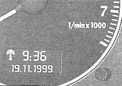
Tachometer
The red range of the scale corresponds to the range of maximum revolutions that are briefly permissible for a run-in and warmed-up engine.
It is recommended to switch to a higher gear or release the gas when the arrow approaches this sector of the scale.
Avoid high speed operation during the break-in period.
Digital watch with date indication
The clock is located on the tachometer and can work as a radio-controlled quartz watch or as a regular quartz watch. The clock is set using a button. In the "radio-controlled quartz watch" mode, a radio information reception symbol appears on the indicator panel (radio tower with diverging waves). In this mode, manual setting of time and date is not possible. If there is no corresponding radio signal for three days, the "quartz watch" mode is automatically switched on. In this case, the radio information reception symbol disappears.
Setting the time
To set the current hour, pull the button until the hour indication digit starts flashing. The hour indication is changed by turning the button left/right.
To set the minutes, pull the button until the minute display digits start flashing. The minute display is changed by turning the button left/right.
Setting the date
Pull the button several times until the day, month and year indication digits start flashing. The day, month or year indication is changed by turning the button left/right.
The time/date setting process is complete when the time/date display digits stop flashing after releasing the button.
Engine oil temperature gauge
Until the oil has warmed up, do not try to use the engine at full power. If, as an exception, the instrument needle enters the upper range of the scale, reduce engine speed. After this, the needle should return to the normal operating range. If the needle remains in the high-temperature range, stop, turn off the engine and check the oil level. If the level is normal and the oil pressure warning light does not flash after starting the engine, then you can, avoiding high engine speeds, drive to the nearest workshop.
Coolant temperature
The indicator works when the ignition is on.
Avoid high revs and engine loads while the needle is on the left side of the scale!
Operating temperature
Under normal driving conditions and coolant temperature, the needle should fluctuate within the middle part of the scale.
Under heavy engine load and high outside temperatures, the needle may be on the right side of the scale. This should not be cause for alarm until the cooling system warning light starts flashing.
Flashing coolant temperature/level indicator light while driving indicates that the coolant level is low or overheating.
Stop, turn off the engine and determine the cause of the malfunction.
Fuel gauge
The indicator works when the ignition is on.
The fuel tank capacity is 70 liters.
If the arrow reaches the reserve scale, this means that there are 9 liters of fuel left in the tank.
The petrol pump symbol on the instrument panel lights up to remind you to refuel. Never run out of fuel before the tank is completely empty.
Speedometer
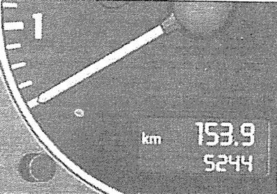
The speedometer is equipped with a digital counter of the total and daily mileage, as well as a display that shows information about the timing of vehicle maintenance.
The upper counter records the total mileage, and the lower one records the mileage since reset.
The accuracy of the mileage measurement is 100 m.
To reset the daily mileage and reset the counter, press the reset button.
Information on maintenance periods
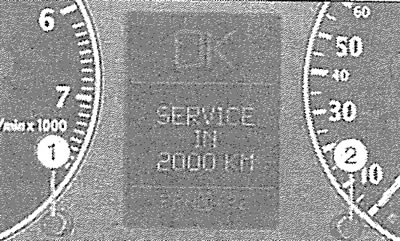
After turning on the ignition and briefly pressing button 1, a message about the number of kilometers until the next maintenance is displayed on the instrument panel.
When the next maintenance period is due, after starting the engine, the display shows the message "SERVICE IN 2000 KM" or "SERVICE!" After approximately 5 seconds, the display switches to the normal display mode.
After performing maintenance or changing the oil in the workshop, new information about the next maintenance periods is entered. The sequence of actions is as follows:
- 1. Turn off the ignition.
- 2. Press button 2 and, while holding it down, turn on the ignition. The display will show the message "SERVICE!".
- 3. Press button 1 until the message "SERVICE!" disappears.
When the battery is disconnected, the maintenance interval information is saved.
If the self-diagnosis system detects faults, the display will show "dEF" instead of the mileage. In this case, you should contact a workshop.
Voltmeter
The voltmeter displays the voltage in the vehicle's electrical system.
The normal voltage value is between 12-16 V. If the voltage drops below 12 V when the engine is running, check the generator and battery. When starting the engine, the voltage may drop to 8 V.
Self-diagnosis system
When the ignition is on, as well as while driving, the self-diagnostic system continuously monitors the functioning and technical condition of certain vehicle systems.
The system notifies the driver of any malfunctions and the need for repair and maintenance work with an audible signal, accompanied by the lighting of signal lights on the instrument panel. The priority of the detected malfunction is indicated by the color of the signal lights, which can be red (1st priority level)or yellow. In addition, text messages can be displayed on the driver's display. The self-diagnostic system also includes a driver alert when the specified speed limit is exceeded.
If the car is equipped with radio equipment at the factory, information about its operation can be displayed on the display.
Red warning signals on the display (1st priority level):
- brake system failure

- coolant level drop or engine overheating

- engine oil pressure drop

The flashing red symbol of the warning light is accompanied by a three-time acoustic signal. In this case, you should immediately stop, turn off the engine, check the system in which the fault was detected, and fix it, possibly by contacting a workshop or calling a tow truck.
If several first-priority faults are detected at once, the corresponding symbols light up on the display sequentially for 2 seconds. The symbols continue to flash until the fault is eliminated.
Yellow symbols (2nd priority level):
- there was only a reserve supply left in the fuel tank

- brake pad wear

- the need to check the engine oil level

- engine oil level sensor malfunction

- headlight range adjuster malfunction

The appearance of a yellow symbol on the display is accompanied by a single sound signal. If several defects are detected at once, the corresponding symbols light up on the display sequentially with an indication duration of 2 seconds. The symbols continue to flash until the fault is eliminated.