
Withdrawal
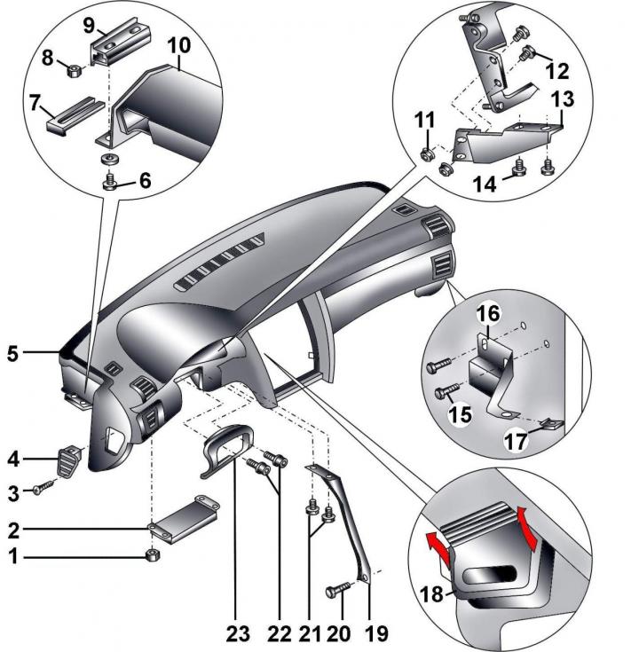
Pic. 16–61. Dashboard: 1 - nut, 6 Nm; 2 - ABS / EDL control unit; 3 - bolt, 1.5 Nm; 4 - ventilation grille; 5 - instrument panel; 6 - bolt, 45 Nm; 7 - gasket; 8 - nut; 9 – an arm of a forward rack; 10 – the basis of the panel of devices; 11 - nut, 10 Nm; 12 - bolts, 10 Nm; 13 – an arm of the panel of devices; 14 - bolt, 22 Nm; 15 - bolt, 7 Nm; 16 - bracket; 17 - nut; 18 - air duct; 19 – an arm of support of the panel of devices; 20, 21 - bolts, 22 Nm; 22 - screws, 2.5 Nm, 23 - lower steering column pad
Cover the driver's and front passenger's seats with a blanket.
Turn on the ignition.
On vehicles with electrically adjustable seats, move them all the way back.
Set the steering wheel to drive straight ahead.
Close the vent flaps by pressing the button «Def» on the air conditioner control panel.
Before disconnecting the battery, find out if you have a radio activation code.
Turn off the ignition and disconnect the wire «masses» from the battery.
Loosen the screws and remove the bottom panel trim with the storage shelf on the driver's side.
Loosen the screws and remove the ventilation grill in the driver's footwell.
Disconnect the electrical connector from the backlight in the driver's footwell and remove the lamp.
Remove glove box.
Remove the front door sill trims.
Remove the center console.
Remove the steering wheel.
Remove the plugs located under the instrument cluster, for which, by pressing, move them to the center.
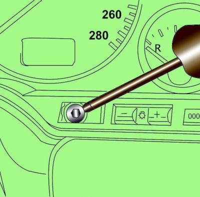
Pic. 16–62. Unscrewing the instrument cluster mounting bolt
Unscrew the two bolts and remove the instrument cluster (pic. 16–62).
Disconnect the electrical connectors from the rear of the instrument cluster.
On models with electric steering column adjustment, disconnect the electrical connector from the steering column adjustment switch. Unscrew the switch mounting bolts and remove it.
Remove the self-resetting ring with electrical connector and sliding ring.
Pic. 16–63. Elements of fastening of switches of a steering column: 1 – the left switch of a steering column; 2 - screw;
3 - clamping bolt; 4 – the right switch of a steering column
Unscrew the top screw 2 (pic. 16–63) securing the steering column switch housing.
Remove the right switch 4 of a steering column together with the wires connected to it.
Loosen the clamping bolt 3 and remove the left switch 1 of the steering column.
Disconnect the electrical connectors from the switches.
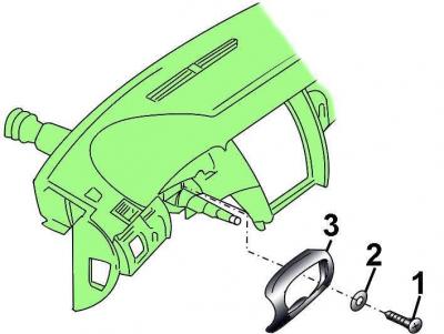
Pic. 16–64. Screw location (1) with puck (2) bottom trim fixings (3) steering column
Turn away screws 1 and remove the bottom overlay 3 of a steering column (pic. 16–64).
On vehicles with automatic transmission, disconnect the cable from the selector lever lock, turn the key in the ignition and remove the cable.
Unscrew the steering column mounting bolts and lower it down. Do not pull the steering column towards you and do not unscrew the steering column universal joint nut.
Unscrew the ABS/EDL control unit from the instrument panel base.
If equipped, separate the auxiliary relay from the instrument panel base.
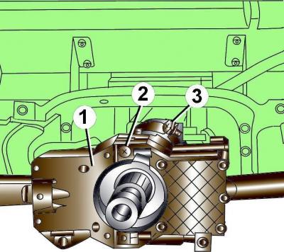
Pic. 16–65. Screw location (1, 3) bracket mounting (2) dashboard support
Unscrew screws 1 and 3 (pic. 16–65) and remove the instrument panel support bracket 2 from the instrument panel base and transmission tunnel.
Disconnect the electrical connector from the headlight range control.
Remove the passenger side airbag.

Pic. 16–66. Bolt location (1) holder attachment (2) to pedal bracket and bolts (3) bottom mount holder
Remove bolts 1 (pic. 16–66) fastening the holder 2 to the pedal bracket.
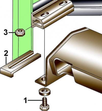
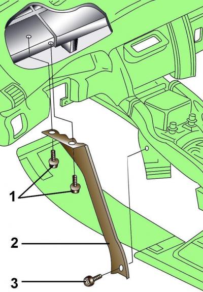
Pic. 16–67. Fastening of the panel of devices to an arm of a forward rack: 1 – a bolt; 2 - gasket; 3 - nut
Unscrew the bolts securing the instrument panel to the brackets of the left and right front pillars (pic. 16–67).
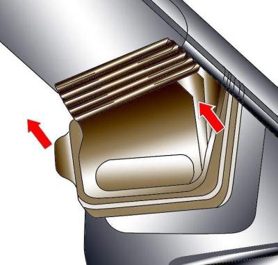
Pic. 16–68. Detachment of the air duct from the casing of the air distributor
Disconnect the air ducts on the left and right side of the air distributor housing (pic. 16–68).
Pull the instrument panel back and remove it. The operation is performed with an assistant.
Installation
Install the dashboard in the car.
Check and, if necessary, adjust the position of the instrument panel in height by selecting gasket 2 (see fig. 16–67) required thickness. The instrument panel should be at the level of the front door upholstery.
Screw in the bolts securing the instrument panel to the brackets of the left and right front pillars (see fig. 16–67).
Loosen bolts 3 (see fig. 16–66) bottom fastening of the holder so that it can be moved.
Screw in the bolts 1 securing the holder 2 to the pedal bracket and tighten them to 22 Nm. Tighten the bolts 3 of the lower mounting of the holder to 10 Nm.
Further installation is carried out in the reverse order of removal.
Visitor comments