
Engine 1.8 l
The engine, together with the manual transmission, is removed downwards. A crane is required to remove the engine/transmission assembly. In no case do not remove the engine/transmission assembly using a garage lift, as this can cause severe engine damage.
Since several connections must be unscrewed on the underside of the vehicle, four stands are required and a lift is required to raise the vehicle. Before installing the engine, the wings in the engine compartment must be protected by covers.
Depending on the year of manufacture of the vehicle and its equipment, electrical wires, as well as vacuum and cooling system hoses, may have a different gasket. Since it is not possible to describe the laying of all possible options here, it is recommended to mark the corresponding lines before disconnecting.
Necessary special tools and auxiliary material:
- Tap
- Clamp for spring clamps, e.g. HAZET 798-5
- Load suspension, e.g. AUDI 2024 A
- MoS2 grease, e.g. AUDI G 000 100
- Torque wrench at 5:50 N•m
- Torque wrench 40:200 N•m
- cable connector
Withdrawal
Warning: Cable connectors that are removed or cut when removing the engine must be reinstalled in their original positions. To do this, it is necessary to mark the places of their installation. To disconnect the connections, press the stoppers and pull the plug.
1. Disconnect the negative cable (-) battery with the ignition off.
Warning: As a result, information is erased from the electronic memory units, such as the code of the radio receiver. Without a code, the radio can only be switched on by the manufacturer or an AUDI workshop. Therefore, read the instructions in the subsection Entering the radio code.
2. Remove the battery, refer to subsection Removing and installing the battery.
3. Turn away bolts of fastening and take out the battery holder.
4. Remove the starter, refer to subsection Check, removal and installation of the traction relay of a starter.
5. Remove the air filter housing, refer to subsection Removing and installing the air filter housing.
6. Turn away bolts of fastening and remove an air line to the air filter on a bumper.
7. Remove the bottom cover of the engine compartment, refer to subsection Removal and installation of the bottom cover of an impellent compartment.
8. Remove the right drive shaft, refer to subsection Removal and installation of power shafts.
9. Disconnect the left drive shaft from the gearbox flange and tie it with wire to the stabilizer or bottom.
10. Drain the coolant, refer to subsection Coolant replacement.
11. Engine 150 hp: Remove the connecting pipes between the turbocharger/charged air cooler, turbocharger/air filter and charge air cooler/intake pipe. To do this, remove the hose clamps.
12. Loosen the tension of the V-belt and remove it, refer to subsections Removing and installing ribbed V-belt And Removing and installing the V-belt.
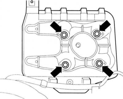
13. Remove the mounting bolts and remove the power steering pump from the holder, tie it with wire to the body. Do not disconnect hoses.
Warning: Do not pinch hoses. If the system was opened during removal, it is necessary to remove air from it, refer to subsection Removal and installation of the power steering pump.
Cars with air conditioning:
Warning: Do not open the cooling circuit of the air conditioner. Skin contact with coolant can cause frostbite.
Warning: Loosen the A/C cooling system clamps. Do not twist, pinch, or bend air conditioner piping or hoses.
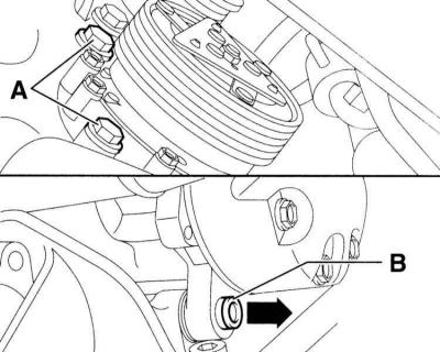
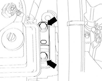
14. Loosen the compressor mounting bolts (A) And (IN) and tie the compressor with wire to the hood latch so as not to stretch the hoses.
15. Remove the exhaust pipe of the muffler and the catalytic converter, refer to subsection Removal and installation of the exhaust system.
16. Disconnect the gas drive cable, do not remove the stopper, refer to subsection Gas Drive Adjustment.
17. Remove the engine cover from the intake manifold.
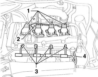
18. Disconnect the plug connections -1- of the ignition coils and -3- of the injectors. Disconnect the negative cable -2-. The accompanying illustration shows a 150 hp engine.
19. Disconnect the vacuum line -4- at the pressure regulator.
20. Disconnect from engine and turbocharger (engines 150 and 180 hp) vacuum and suction hoses. If necessary, mark the hoses and fittings to avoid assembly errors.
21. Disconnect all plug connections from the engine and manual transmission to the body.
Warning: The fuel system is under pressure! Before opening hose connections, cover them with a thick cloth. Then carefully release the pressure. Wear protective goggles. Danger of splashing!
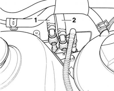
22. Disconnect the supply lines -1- and return lines -2- at the fuel distributor by pressing the release buttons on the coupling. Mark hoses with tape for easy reassembly.
23. Cover the fuel lines with film and rubber rings to prevent dirt from entering the system.
24. Disconnect 2 coolant hoses to the heater heat exchanger at the front wall of the engine compartment, for which open the clamps.
25. Remove all coolant hoses from the engine to the top and to the expansion tank by opening the clamps and removing the hoses.
26. Remove the fan with holder, refer to subsection Removal and installation of a radiator and fan.
27. Vehicles with manual transmission: Remove shift actuators and clutch cylinder.
Warning: After removing the clutch slave cylinder, do not depress the clutch pedal.
28. Cars with AT: Turn away bolts of fastening and remove the holder of the pressure head pipeline of the hydraulic booster at a support of a box. Remove the selector cable from the gearbox, refer to subsection Adjustment of a cable of the selector of switching of automatic transmission.
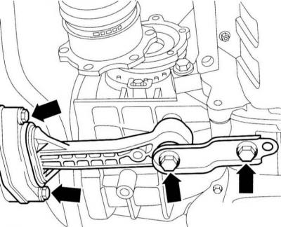
29. Turn away bolts of fastening of a pendular support below between a body and the block the engine/transmission.
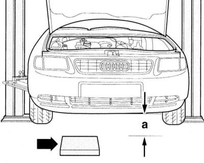
30. Raise the vehicle. It should be at least a = 60 mm from the ground.
31. Lay a wooden block on the ground (arrow) with dimensions of 40 x 30 cm and a thickness of 15 cm for installing an engine on it in the area of \u200b\u200bthe oil pan.
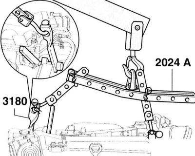
32. Connect the AUDI-2024A lifting device to the eye hook 3180 on the engine. Connect the vertical perforated bars to holes 1 and 5 of the cross bar. Insert a finger from the flywheel side of the engine into the second hole of the tire, from the pulley side into the third hole. Holes are counted from the hook side.
Warning: Use locking pins on hooks and locking pins. Perforated bars must be properly aligned in length to match the machine's center of gravity.
33. If a suitable lifting device is not available, a chain can be used to lift the machine.
34. Raise the engine/gearbox assembly with a crane to relieve the engine mounts.
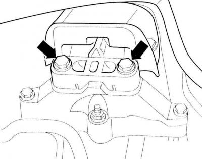
35. Unbolt the right engine/gearbox mount from above.
36. Turn away bolts of fastening of a support of a box at the left.
37. Check that all hoses and pipes from the engine and gearbox to the chassis have been disconnected.
38. Pull the engine/transmission assembly forward as far as possible and slowly lower it onto the wooden spacer. Perform the operation carefully so as not to damage the mechanisms.
Warning: Secure the block so it does not tip over.
39. If necessary, disconnect the box from the engine, refer to subsection Removal and installation of manual transmission.
Installation
40. Check for pores and cracks in engine rubber mounts and cooling, oil and fuel hoses. Replace if necessary.
41. Only if the engine has been disconnected from the box: Check the clutch. Insert the engine/gearbox mounting bolts and tighten to the specified torque. In doing so, follow the instructions in the subsection Removal and installation of manual transmission.
42. Reinstall the engine/gearbox assembly and hand-tighten with new bolts.
43. Fasten the pendulum arm by hand with new bolts.
44. Expose the block the engine/box by strong rocking of its hands.
45. Fasten the engine/gearbox and swing arm mounts to the torque values given in the Specifications. In this case, first tighten all the bolts with a torque wrench and then tighten the bolts with a hard wrench at an angle of 90° (1/4 turn).
Warning: Bolts will permanently elongate when tightened. Therefore, after each tightening, new bolts should be used.
Warning: Before tightening, measure the thread diameter of the bolt as it depends on the tightening torque.
46. If the air conditioning compressor was removed, secure it with a torque of 45 Nm.
47. Fix the power steering pump, refer to subsection Removal and installation of the power steering pump.
48. Install the starter, refer to subsection Removal and installation of a starter.
49. Put on the V-belt and tighten it, refer to subsections Removing and installing ribbed V-belt And Removing and installing the V-belt.
50. Attach the air duct to the air filter at the lock holder.
51. Install the air filter housing, refer to subsection Removing and installing the air filter housing.
52. Engine 150 HP: Install connecting pipes between the turbocharger/charge air cooler, turbocharger/air filter and charge air cooler/intake pipe. Secure the hoses with clamps.
53. Install the exhaust pipe/catalytic converter with new seals, refer to subsection Removal and installation of the exhaust system.
54. Install the left and right drive shafts, refer to subsection Removal and installation of power shafts.
55. Connect the gas actuator and adjust it, refer to subsection Gas Drive Adjustment.
56. Put on a distributive pipe giving and returnable fuel lines. The quick couplings must be clearly engaged.
57. Install the heater hoses from and to the heat exchanger against the front wall of the engine compartment. Secure them with clips.
58. Install the radiator fan with holder, refer to subsection Removal and installation of a radiator and fan.
59. Cars with manual transmission: Reinstall the shift actuators and adjust them, refer to subsection Gearshift drive.
60. Install the working hydraulic cylinder of the clutch drive on the manual transmission, refer to subsection Removal, installation and clutch check.
61. Cars with АТ: Fix the holder of the pressure head pipeline of the hydraulic booster on a support of a box. Install the selector rod on the box and adjust it, subsection Removal, installation and clutch check.
62. Connect the electrical wires in accordance with the markings applied during removal and fix them.
63. Fasten the electrical wires in place of their previous fastening. Secure them with clamps.
64. Reinstall and secure the battery holder.
65. Install the battery without connecting the negative cable yet, refer to subsection Removing and installing the battery.
66. Check that electrical wires, vacuum hoses, coolant hoses and fuel hoses are connected according to their markings.
67. Check the oil level in the engine and gearbox, top up if necessary.
68. Check the presence of antifreeze in the coolant and top up if necessary, refer to the subsections Coolant replacement And Checking fluid levels, leak control.
69. Install the engine cover to the intake manifold.
70. Establish the bottom cover of an impellent compartment, address to subsection Removal and installation of the bottom cover of an impellent compartment.
71. Connect ground cable (-) battery.
Warning: Activate the height automatic power window, and also set the clock and enter the radio code, refer to the subsection Entering the radio code.
72. Start and warm up the engine to operating temperature. Check oil and coolant levels. Check all hose connections for leaks.
73. Check headlight adjustment, refer to subsection Headlight adjustment.
Warning: When disconnecting the various electrical connections, faults are recorded in the control devices, which must be removed after installation. Since this requires an electronic tester that connects to the vehicle's diagnostic connector. For this purpose, you must contact the service station.
Visitor comments