
Withdrawal
Before disconnecting the battery, find out if you have a radio activation code.
Turn off the ignition and disconnect the wire «masses» from the battery.
Loosen the four screws and remove the engine cover (see fig. 3.1–41).
Loosen the clamps and remove the air pipe connecting the air mass meter and the suction pipe.
Disconnect electrical connectors for lambda sensors.
Unscrew nuts of fastening of the right and left reception exhaust pipes.
Unscrew the top bolts of fastening of a transmission to the engine.
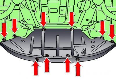
Pic. 3.1–1. The location of the fastening latches of the lower mudguard of the engine compartment
Release the clips and remove the lower mudguard of the engine compartment (see fig. 3.1–1).
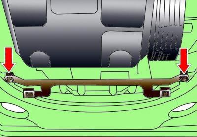
Pic. 3.1–2. Arrangement of bolts of fastening of an arm of the lower mudguard of a motor compartment
Unscrew the two bolts and remove the bracket for the lower mudguard of the engine compartment (see fig. 3.1–2)
Unscrew the bolts and remove the protective covers located above the left and right drive shafts.
Unscrew bolts and disconnect internal hinges of shafts of a drive from a transmission. Using a soft wire, hang the inner ends of the drive shafts from the body.
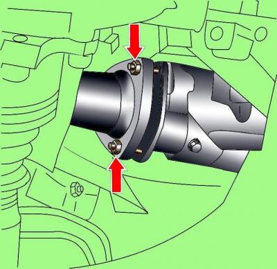
Pic. 9–1. Arrangement of bolts of fastening of a reception exhaust pipe to catalytic converter
Unscrew the bolts securing the left and right exhaust pipes to the catalytic converter (pic. 9–1).
Release the exhaust pipe connectors and remove the exhaust pipes and catalytic converter.
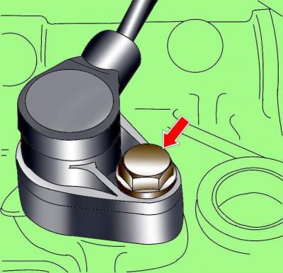
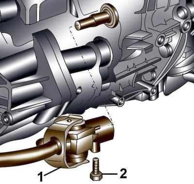
Pic. 9–2. An arrangement of a bolt of fastening of the gauge of frequency of rotation of the engine
Unscrew the engine speed sensor from the front left side of the gearbox (pic. 9–2).
Disconnect the electrical connector
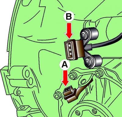
Pic. 9–3. Location of the electrical connectors of the speedometer sensor (A) and reverse switch (IN)
A (see fig. 9–3) from the speedometer sensor.
Disconnect the electrical connector IN (see fig. 9–3) from reverse switch (multifunction sensor).
Disconnect the remaining connectors and the wire connecting to «weight» from the gearbox.
Unscrew the starter mounting bolts, remove it and fix it on the engine without disconnecting the wires from it.
Pic. 9–4. Fastening of draft to a rod of a gear change: 1 – draft; 2 - bolt
Unscrew the bolt and remove the rod from the gear shift rod (pic. 9–4).
Unscrew the bottom bolts of the gearbox to the engine, with the exception of the bolts located on the sides of the gearbox flange.
Mount the special tool on a stationary jack, place it under the gearbox and raise the jack until the weight of the gearbox is supported by the jack.
If there are no special tools for removing the gearbox, support the gearbox with a jack through a block of wood.
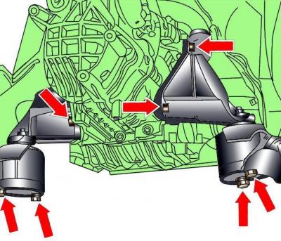
Pic. 9–5. Arrangement of bolts of fastening of the left and right support of a transmission
Unscrew the bolts securing the left and right gearbox supports (pic. 9–5).
Unscrew the remaining two lower bolts securing the gearbox to the engine.
Move the gearbox away from the engine and lower it 15 cm to expose the clutch slave cylinder.
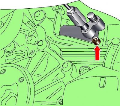
Pic. 9–6. Location of the clutch slave cylinder bolt
Unscrew the slave cylinder and attach it to the body with soft wire (pic. 9–6). Do not disconnect the hydraulic hose from the working cylinder and do not press the clutch pedal.
Being careful, lower the transmission and remove it from under the vehicle.
Installation
Installation is carried out in the reverse order of removal, taking into account the following.
Check the condition of the clutch.
Clean the spline of the gearbox input shaft and lubricate with a thin layer of special grease G 000 100. The lubrication layer must be thin and even, otherwise, during clutch operation, excess lubricant will be thrown onto the clutch working surfaces, which can disrupt its operation.
Apply a light coat of grease to the pushrod head that mates with the clutch release lever.
Make sure that guide bushings are installed in the engine block to center the gearbox.
Raise, attach the gearbox to the engine and install the clutch slave cylinder.
Move the gearbox towards the engine so that the gearbox input shaft fits into the splines of the clutch disc. It may be necessary to turn the engine crankshaft slightly to align the gearbox input shaft splines with the clutch driven plate splines. When installing the gearbox, the drive shaft must not hang on the clutch disc.
With the transmission moving forward, install the clutch housing on the guide bushings of the cylinder block.
Insert the bolts securing the gearbox to the engine and at this stage tighten them to a torque of 25 Nm.
Install starter.
Tighten bolts of fastening of a transmission to the engine the demanded moment.
Connect the connection wire to «weight» to the gearbox.
Screw in bolts of fastening of support of a transmission (see fig. 9–5).
Remove the gear box jack.
Connect the drive shafts to the gearbox.
Install the drive shaft guards and secure them with bolts.
Install and screw the control rod to the gearbox.
Connect the tachometer and reversing light electrical connectors to the transmission.
Install the exhaust pipe.
Check and, if necessary, top up the oil level in the gearbox.
Connect wire «masses» to the battery.
Turn on the radio and enter the code into it.
Raise the windows with the power windows up to the stop. Then press all power window switches again for at least 1 second to the closed position to activate the power window control unit.
Set the time on the clock.
Before starting the engine, check the presence and level of engine oil in the engine.
Tightening torques, Nm
| Selector cable bracket to gearbox | 23 |
| Selector cable to lever | 5,6 |
| Selector cable sheath to bracket | 12 |
| Torque converter to pressure plate | 85 |
| Engine torque compensator stop to frame | 40 |
| Torque compensator support to engine | 42 |
| Gearbox support to lower frame | 40 |
| Drive shaft to transmission drive flange | 77 |
| Heat shield for drive shaft to gearbox | 23 |
| Generator to engine: | |
| M8 | 22 |
| M10 | 45 |
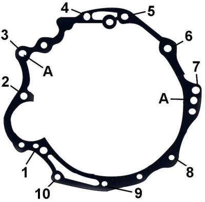
Pic. 9–7. Location and numbering of bolts for fastening a manual transmission to a 2.8-liter gasoline engine: A - the location of the centering sleeve
| Position | Bolt | Tightening torque, Н·м |
| 1 | M10x135 | 45 |
| 2 | М12х110 | 65 |
| 3, 4, 5 | М12х67 | 65 |
| 6 | М12х90 | 65 |
| 7 | М12х80 | 65 |
| 8 | M10x50 | 45 |
| 9 | М10х38 | 45 |
| 10 | М8х40 | 20 |

Pic. 9–8. Location and numbering of bolts for fastening a manual transmission to gasoline engines of 3.7 and 4.2 liters: A - installation location of the centering sleeve
| Position | Bolt | Tightening torque, Н·м |
| 1 | М12х75 | 65 |
| 2 | М12х110 | 65 |
| 3 | М10х45 | 45 |
| 4 | М12х90 | 65 |
Visitor comments