



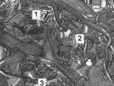
The power unit is removed and installed on the "VAS 6131 A" lift. Remove plug connection "3" from the holder and disconnect it, releasing the wire. Disconnect electrical connector "2", disconnect differential pressure sensor "G505" from the bracket and release it. "Pos. 1" should not be taken into account.
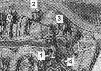
Remove connectors "1, 4" from the bracket and disconnect it. "Pos. 2, 3" do not take into account.
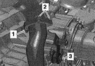
Unscrew bolt "3". Ignore "Pos. 1, 2".
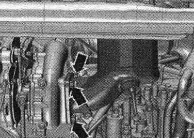
Unscrew the nuts of the particulate filter and turbocharger arrows. Remove the diesel particulate filter with the exhaust pipe.
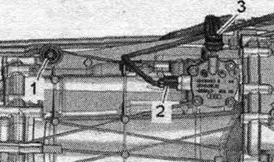
Disconnect the plug "2" of the gear detection sensor "G604" and release the wire. "Pos. 1, 3" do not take into account.
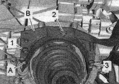
Remove bolts "1" and "3". Loosen bolt "2" and set heat sink "B" aside. - Ignore pos. A.
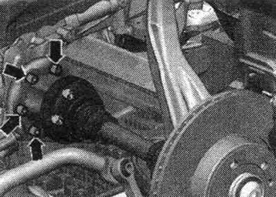
Unscrew the left and right CV joint shafts from the transmission flange shafts. Disconnect the G28 engine speed sensor electrical connector on the transmission.

Remove cover "1" from the bottom of the "arrow" gearbox.
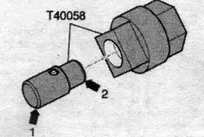
Insert the guide pins of the adapter "T40058" as shown below: the large diameter "arrow 1" faces the engine, the small diameter "arrow 2" faces the adapter.
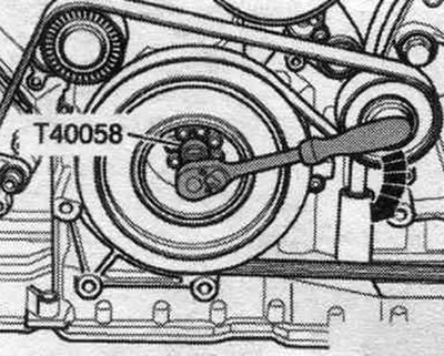
Hold or turn the crankshaft to loosen the clutch module mounting bolts using the adapter "T40058". During the final turn, rotate the crankshaft only in the direction of engine rotation "arrow".
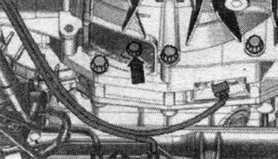
Unscrew the 6 bolts "arrow" of the clutch module, to do this, turn the crankshaft accordingly through 60° in the direction of engine rotation.
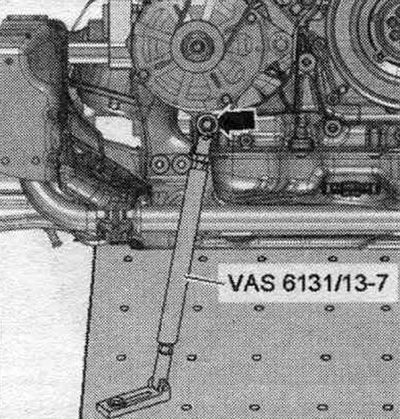
Prepare the lifting table -VAS 6131 A- with a set of fastenings for "VAS 6131/10", conductor "VAS 6131/13-7" and the gearbox lock "VAS 6131/14" as follows. Other fasteners remain unchanged. Secure the conductor "VAS 6131/13-7" on the front right side of the engine, screwing the M12x35 "arrow" bolt into the threaded hole, as shown in the figure. If the hole is not threaded, it must be threaded. Secure the jig to the VAS 6131 A lifting table with a torque of 20 Nm.
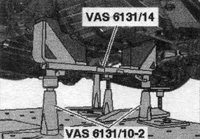
Install conductors from "VAS 6131/10" and the gearbox lock "VAS 6131/14" in front of the checkpoint, as shown in the figure. Turn the right and left lead screws upwards so that the gearbox lock "VAS 6131/14" fits snugly against the gearbox. Screw the support plates of the fastening elements to the "VAS 6131 A" lifting table with a torque of 20 Nm.
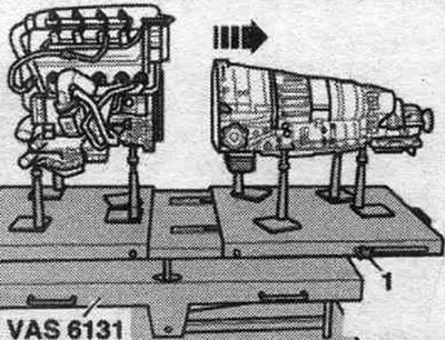
Loosen bolts "1" and "2" of the starter. Press the starter away from the gearbox and leave it in the mounting position. position. Loosen the remaining bolts "3...11" securing the engine to the gearbox. Ignore "Pos. A.". Unscrew the clamping bolts "1" on the side of the lifting table "VAS 6131 A" and move the rear platform with the gearbox back "arrow".