



More details see previous engine.
Remove the engine from the manual transmission
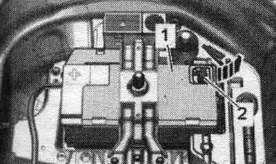
The engine with gearbox and accessory bracket is removed downwards with the radiator frame installed. When reassembling, install all binders in the places where they were originally installed. Set the front wheels to the straight-ahead position. Follow the instructions when disconnecting the battery terminals. Turn off the ignition. Disconnect ground wire "2" from the battery terminal. Drain the air conditioning circuit.
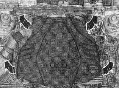
Remove the "arrow" engine cover.
Drain the air conditioning circuit. Open the expansion lid. tank.
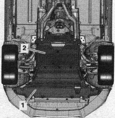
Remove the front wheels on the left and right. Remove the front right and front left fender liner. Remove noise insulation screens "1" and "2".
All-wheel drive vehicles: remove the propeller shaft.
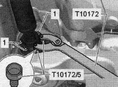
Place a service tray under the engine. Unscrew the "arrow" plug on the connecting pipe and drain the coolant. Then remove the connecting nipple from the radiator by loosening the mounting bracket 2.
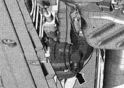
Remove the coolant hose from the branch pipe on the bottom left, loosening the hose clamp "arrow", and drain the coolant.
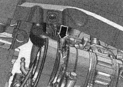
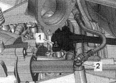
Disconnect plug "1" of the boost pressure sensor "G31"/intake air temperature sensor "G42" and release the electrical wire. "Pos. 2" should not be taken into account.
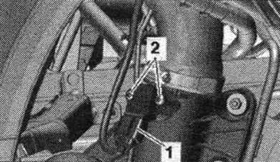
Unscrew the "arrow" nut on the right side member and release the ground cables.
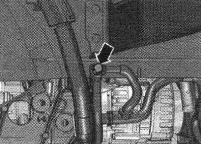
Disconnect the plug connector "1" and, if present, "2" of the radiator fan. To do this, move the fuse back "arrow" and press the lock down. Release the electr. wiring harness.
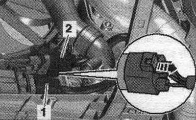
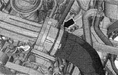
Disconnect the air duct hose from the air duct and place it aside; to do this, loosen the "arrow" clamp.
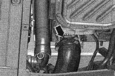
On a car with an independent heater, unscrew nut "1", open clamp "3" and remove exhaust pipe "2" of the independent heater.
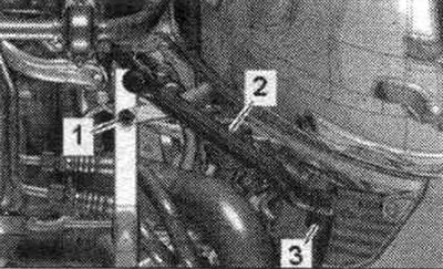
Unscrew bolts "1" and nuts "3" on the left and right and remove the radiator frame cross members "2".
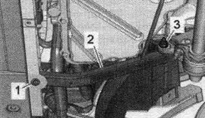
Remove the "arrow" air duct.
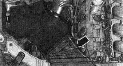
Disconnect the "1" connector from the "G70" air flow meter. Remove the air duct hose with the "G70" air flow meter by loosening the "2" hose clamp and loosening the "arrow" fasteners.
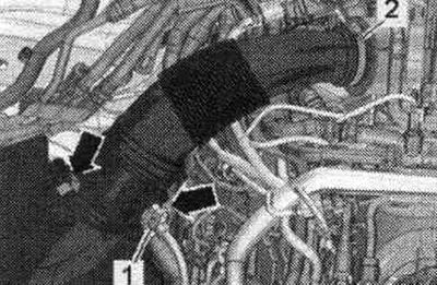
Disconnect vacuum line "1". Remove air intake housing. filter, disconnect the plug connector "2" of the air bypass valve on the back side. filter "N275" and release the electrical wire.
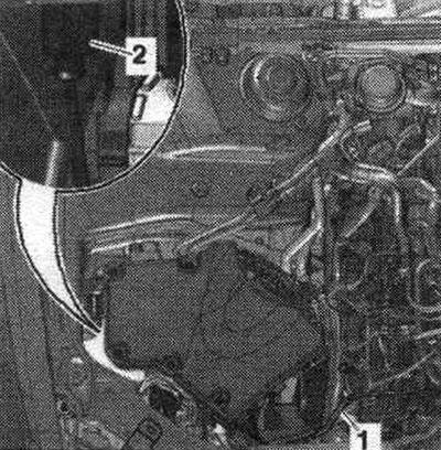
Remove the fuel hoses by loosening the hose clamps.
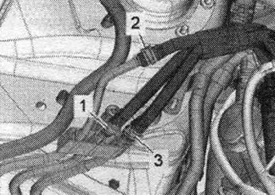
1. Fuel hose, blue. 2. Fuel hose, blue. 3. Fuel hose, white.
Remove the coolant hose from the front pipe of the system. cooling, releasing the "arrow" clamp.
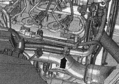
Remove the air duct hose by loosening the hose clamps "arrows".
Unscrew bolt "2", remove the refrigerant line from the compressor and put it aside. Close open lines and pipes with clean plugs from the engine plug kit "VAS 6122". "Pos. 1, 3" do not take into account.
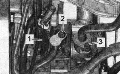
Remove coolant hose "3" from the expansion tank. Ignore "Pos. 1, 2" and "arrows".
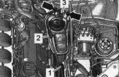
Remove the seal from the front wall of the water drainage box. Remove the cover of the water drainage box.
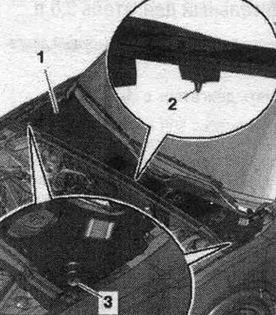
Unlock the lock "arrow A" and open the cover "arrow B".
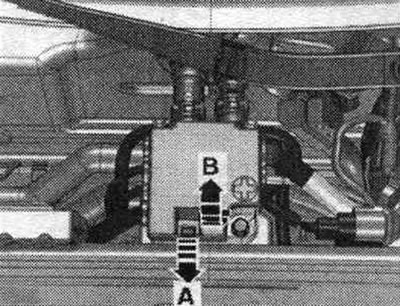
Loosen the nuts "1...4" of the wires. Remove the plug connection "5" from the holder and disconnect it. Unscrew bolt "6" and remove branch pipe 2 cl. 30 "TV22" from the "arrow" stretcher.
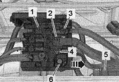
Unlock the retainers from the wheel arch using a 5.5 open-end wrench "pos. 1" and remove the cable entry "2" upwards. Release the wiring harness "3" to the generator and starter using the release lever "80-2000".
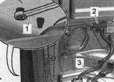
Open cable channel "1" by unfastening the "arrow" clamp and releasing the wiring harness.
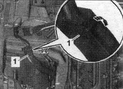
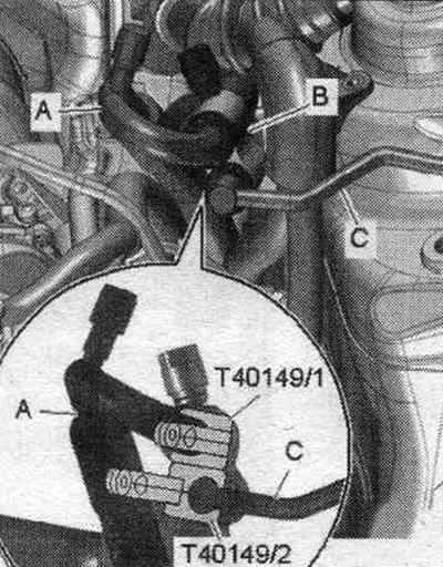
Remove refrigerant lines "A" and "C" from the indoor heat exchanger.
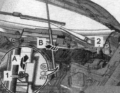
Unscrew the nut "1" and tilt the filler neck of the washer fluid reservoir slightly upwards "arrow A". Remove the filler neck "2" with the filler tube from the washer fluid reservoir, passing it through the body opening "arrow B".
On a car with an independent heater, unscrew bolts "2" and put aside pump block "1".
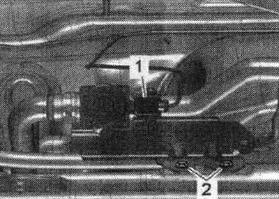
Unscrew bolts "1" and nuts "2" and remove stretcher "3".
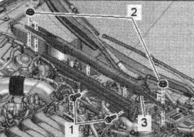
Unscrew the arrow bolts and remove the cover of the motorcycle switching unit. compartment. Unscrew nut "1" and release the wire.
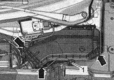
Remove the fasteners "arrow A" and open the cover "arrow B" of the engine control unit.
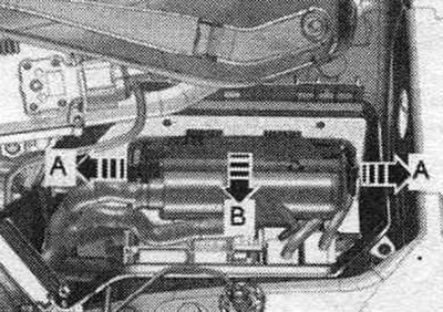
If present, disconnect plug connection "2". Disconnect plug connectors "4" and unscrew nut "3" securing the drive. Remove the "arrow" fasteners and the fasteners for the relay with the fuse holder "1". Disconnect the engine wiring harness from the switch. block in motorcycle. compartment and release it.
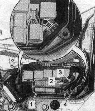
Unlock the clamps "arrow A" and remove the cable guide "1" in the upward direction "arrow B". Loosen the ground bolt "2" and release the wiring harness. Place the wiring harness on the engine and secure the engine control unit from falling out.
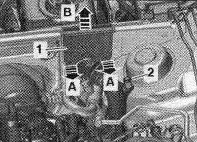
Disconnect the system hose. cooling system, to do this, loosen clamp "1". Remove vacuum pipe "2" from the end wall of the water drain box, to do this, disconnect vacuum hose "3" on the back side "arrow".
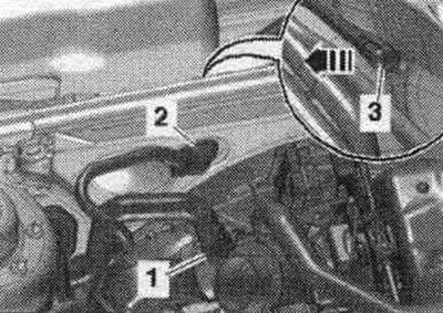
Disconnect the "arrow" connectors from the front speed sensors on the left and right.
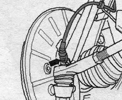
If available, disconnect connectors "1" of the front left vehicle level sensor "G78" and the front right vehicle level sensor "G289" and release the electrical. "Arrow" cable.
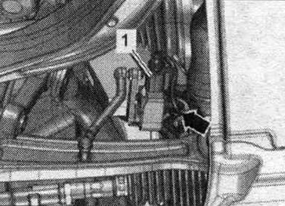
Release the plug connector "2" from the bracket by pulling the locking tab back "arrow A" and turning the connector approx. 90° clockwise "arrow B". Release wire "3" and brake hose "4" on the bracket. Unscrew bolts "1" and hang the brake. caliper with connected brake. hose in the wheel well. Do not press the brake pedal when the brake is released. support.
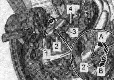
Unscrew the nut "2" and remove the bolt "1". Remove the upper guide of the axle strut from the wheel bearing housing upwards "arrow". Repeat the entire work process on the other side of the vehicle.
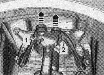
Unscrew the stabilizer bolt "1" on the left and right. Unscrew nuts "3" on the left and right. Bolts "2" are removed later.
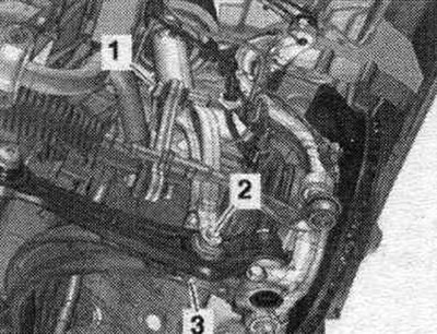
Remove the subframe crosspiece.
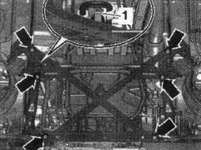
Unscrew the left and right arrow bolts and remove the heat shield "1".
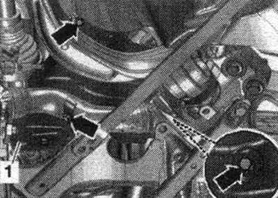
Disconnect electrical connector "2" on the power steering control unit "J500", disconnect the fuse "arrow" and press the lock down. Disconnect electrical connector "1" on the power steering control unit "J500". Release the wiring harness.
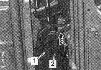
Remove the intermediate shaft from the steering gear and move the engagement.
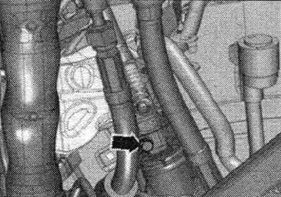
Unscrew bolt "2" and tie the clutch slave cylinder to the side of the motorcycle. compartment. Unscrew nut "1" of the switching rod.
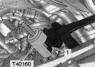
Install the puller "T40160" and remove the shift rod "1".
Prepare the lifting table: Equip the lifting table "VAS 6131 A" a set of fasteners for "VAS 6131/10" and additional set "VAS 6131/13" as follows. First, screw the conductors to the lifting table by hand. Install the lifting table "VAS 6131 A" horizontally. Monitor the level (peephole) on the receiving platform. Place the lifting table "VAS 6131 A" under the power unit. Unscrew the bolts "1" of the subframe on the left and right.
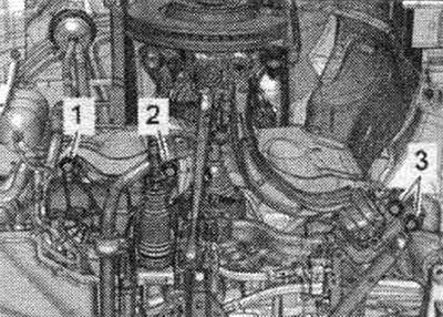
Install conductors from "VAS 6131/10" and "VAS 6131/13" left and right on the front part of the subframe, as shown in the figure. Make sure the lead screws are fully screwed in.
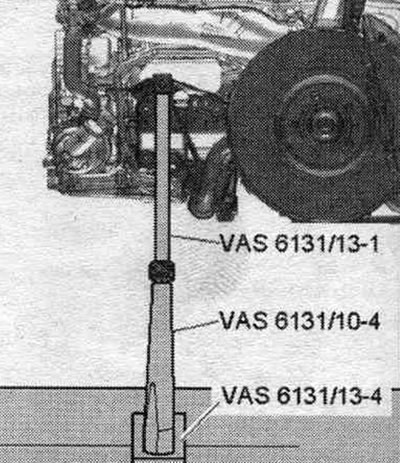
Install conductors from "VAS 6131/10" at the rear left and right on the front threaded connections of the subframe strut, as shown in the figure.
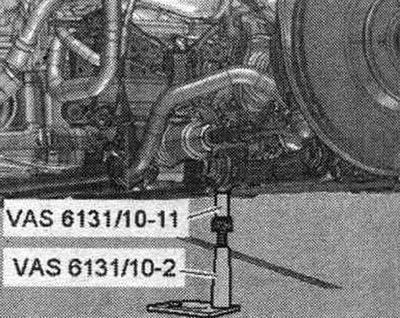
Install conductors from "VAS 6131/13" left and right on the lower part of the wheel hub bearing housing, as shown in the figure.
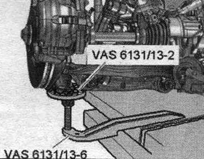
Remove the noise insulation screen clamps from the tunnel cross member. Install the fastening elements from "VAS 6131/10" left and right at the rear on the tunnel crossbar, as shown in the figure.
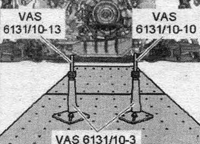
Install the fastening elements from "VAS 6131/10" and "VAS 6131/13" under the receiving pipe, as shown in the figure. Turn all the lead screws of the conductors upwards so that all the mounting protrusions enter the mounting points. Screw the support plates of the fastening elements to the VAS 6131 A lift with a torque of 20 Nm.
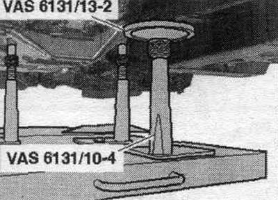
Front wheel drive vehicles: Loosen the arrow connections and move the clamping sleeve back.
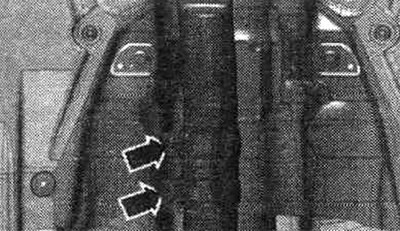
Mark the mounting on the side members with a felt-tip pen. position of the subframe and tunnel crossmember. Loosen bolts "2" and "3" of the subframe crosswise in several stages.
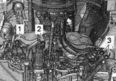
Unscrew the bolts of the tunnel cross member "arrow".
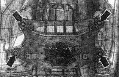
Loosen bolt "2" on the left and right. Make sure all hose and wire connections between the engine, transmission, subframe, and body are disconnected. When lowering, carefully remove the power unit with the subframe from the motorcycle. compartment. Carefully guide the shock absorber strut to the side members.
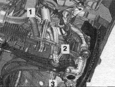
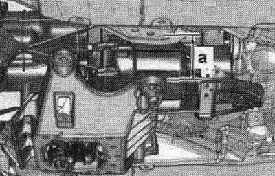
Lower the power unit using the VAS 6131 A lifting table only by dimension "a". Dimension "a" = max. 100 mm.
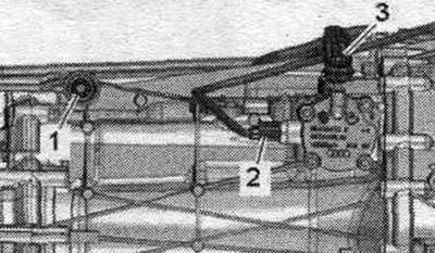
Unscrew bolts "1" and "3" of the engagement rod and gear selection rod. "Pos. 2" should not be taken into account. Lower the power unit lower. Remove the lifting table "VAS 6131 A" with the power unit from under the vehicle.
The full version is posted on the resource: AUDImanual.ru