



Tightening torques (Nm)
| Bolts and nuts | M6 | 9 |
| M7 | 15 | |
| M8 | 20 | |
| M10 | 40 | |
| M12 | 65 |
Engine for manual transmission/multitronic CMV/dual clutch transmission 0B5
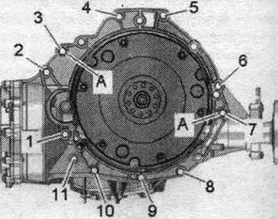
| Pos. | Bolt | Nm |
| 1 (1) | M10x50 (2) | 65 |
| 2 (1)...6 | M12x100 (3) | 30 + 90° |
| 7 | M12x125 (3) | 30 + 90° |
| 8, 11 | M10x60 (3) | 15 + 90° |
| 9, 10 | M10x95 (3) | 15 + 90° |
| a | Centering bushings | |
(1) Additionally secures the starter.
(2) Bolt strength class 10.9. Steel bolt can be used repeatedly.
(3) Aluminum bolts can be used twice.
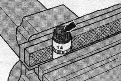
Aluminum bolts "2...11" may be used no more than 2 times. Therefore, after the first use, mark such bolts with 2 notches "X" "arrow". To avoid damaging the bolts when making the notches, do not clamp them in a vice. Insert the bolt as shown in the picture into the 14mm socket using a 1/2' drive, which can then be secured in a vice. Bolts marked with "X" must not be reused.
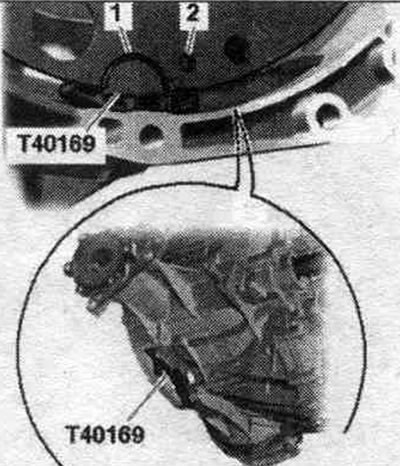
Replace bolts that were tightened with additional tightening. Replace self-locking nuts, lip seals, gaskets and seals. rings. Remove plugs or protective caps only immediately before installing the corresponding line. To secure all hose connections, use clamps of the appropriate series. During installation, all cable ties should be placed in their original locations. Be sure to clean the threaded holes for fixing the power unit in the cylinder block before assembling the gearbox with a tap. Before connecting the engine and gearbox, perform the following preparatory steps: Insert the mounting. insert the T40169 tool into the gearbox housing from below and install the clutch module/dual mass flywheel as shown in the figure. Mounting tool "T40169" should fit into semicircular groove "1" and additionally into inspection hole "2." To locate the inspection hole, it is necessary to rotate the clutch module/dual mass flywheel.
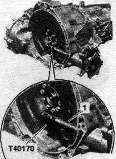
Insert mounting bolts. device into the hole in the gearbox housing. Install the "T40170" transport protection underneath the gearbox housing and attach it to the shaft with flange "1.".
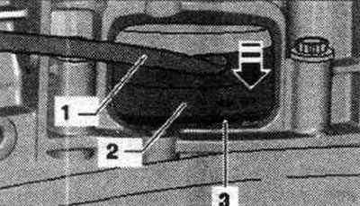
Check the presence of the engine and gearbox center bushings "A" in the cylinder block; insert the bushings if necessary. Check the aluminum engine-to-gearbox mounting bolts for reuse and, if necessary, mark them. Install the gearbox on the engine and tighten bolts "1...11." Remove transport lock "T40170" and mounting tool "T40169." This step ensures that the clutch module/dual mass flywheel fits evenly on the driven disc and does not warp. Lightly press the clutch module/dual-disc flywheel "2" with the crowbar "1" to the driven disk "3" "arrow".
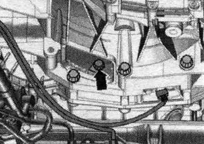
Secure the clutch module/dual mass flywheel to the driven disc as follows. To tighten the bolts, use a SW16 ring spanner - VAG 1332/14-. Screw in the first bolt "arrow" by hand (2 Nm).
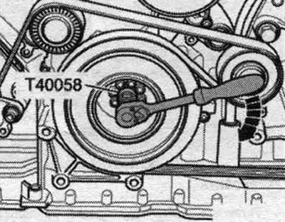
Insert the guide pins of the adapter "T40058" as shown below: the large diameter "arrow 1" faces the engine, the small diameter "arrow 2" faces the adapter. Turn the crankshaft using the T40058 adapter by 180° in the direction of engine rotation "arrow".
In this position of the crankshaft, tighten the accessible bolt "arrow" to the specified torque.
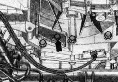
Turn the crankshaft 60° and tighten the remaining 5 bolts to the specified tightening torque. When installing the engine on the subframe, hold the ATF lines in the mounting position. Install the engine mount and cushion. Bolt the left and right drive shafts to the axle shafts with transmission flanges. Vehicles with a 0AW multitronic transmission: install the ATF lines. Vehicles with an 0B5 dual-clutch transmission: install the ATF lines. Install the diesel particulate filter.
Vehicle with manual gearbox and dual-clutch gearbox 0B5: First lift the power unit with the lifting device "VAS 6131 A" far enough so that the dimension "a" remains between the tunnel crossmember and the body. Gap dimension "a" = at least 100 mm.
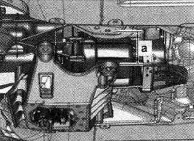
Cars with manual transmission: install the engagement rod and gear selection rod. Vehicles with dual clutch transmission 0B5: Install the selector cable.
All
Raise the power unit using the lifting table -VAS 6131 A-. Align the subframe and tunnel crossmember in accordance with the markings made on the side members during dismantling. Tighten the subframe bolts only with a light torque, do not tighten at an angle (tighten the bolts only after checking the wheel alignment angles). Tighten the tunnel crossmember bolts. Installation in reverse order. All-wheel drive vehicle: install the propeller shaft. Cars with manual transmission: install the clutch slave cylinder. Install the front cross member. Cars with multitronic 0AW gearbox: install the selector cable. Tighten the intermediate shaft onto the steering gear. Install the subframe brace, upper suspension arm, stabilizer bar and, if necessary, diagonal strut, tighten the shock absorber strut mounting bolts on the control arm. Install brake. support. Install the engine control unit. Install the washer reservoir filler neck. Install the wires, the 2-way splitter 30 "TV22" and the cover of the motor junction box. compartment. Install the refrigerant lines. Do not use a battery charger to start the engine! Install the air intake housing. filter. Install the radiator frame cover. Install the water drain box cover and radiator frame spacer. Fill with oil and check its level. Connect the coolant hoses using the union nut. Fill with coolant. Bleed the air from the system. power supply. Fill the air conditioning circuit. Install wheel arches. Install the front wheel. Perform a RUUK. Fill with ATF. Install noise insulation screens.
(Material republished from the website: AudiManual)