
Table of contents: Cylinder head, 2.0 l engine (with… ↓ Crankcase ventilation - sequence,… ↓ Removal and installation the… ↓
Cylinder head, 2.0 l engine (with free play of the bolt)
Note: Replace the cylinder head mounting bolts. When performing installation work, replace the self-locking nuts, bolts that require additional tightening, and seals. rings and seals. The plastic linings included in the repair kit for protecting exposed valves may be removed immediately before installing the cylinder head. If the cylinder head or head gasket was replaced, the coolant and oil must be changed.
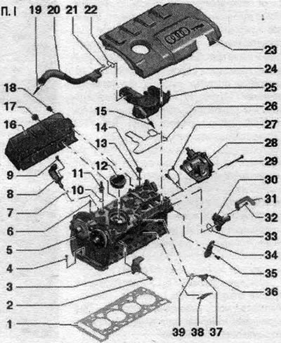
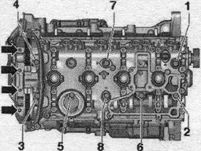
1. Cylinder head seal: replace; take into account mont. position: cylinder head part number. 2. Bolt: 25 Nm. 3. Transport eye. 4. Bolt: tighten in 2 stages: 1) tighten to a torque of 8 Nm, 2) turn further 90° with a regular wrench. 5. Cylinder head. 6. Cylinder head bolt: replace; take into account the sequence of actions when unscrewing; follow the procedure for tightening; tighten in 3 stages: 1) tighten to a torque of 40 Nm, 2) tighten further by 90° with a regular wrench, 3) tighten further by 90° with a regular wrench. 7. Sealing ring: replace, lubricate with oil. 8. Executive element of the phase shifter. 9. Bolt; 5 Nm. 10. Sealing ring: replace, lubricate with oil. 11. Plug: 5 Nm; with ball head for engine casing. 12. Lid: with seal. 13. Sealing ring: replace, lubricate with oil. 14. Plug. 15. To the intake manifold. 16. Thermal insulation shield. 17/18. Bolt: 20 Nm. 19. To the intake manifold/turbocharger. 20. Ventilation pipe. 21. Sealing ring: not a spare part. 22. Gasket: not a spare part. 23. Engine casing. 24. Bolt. 25. Crankshaft crankcase ventilation. 26. Gasket: not a spare part. 27. Gasket: replace if damaged. 28. Vacuum pump. 29. Bolt. 30. Connecting pipe. 31. Mounting plate. 32. Bolt: 9 Nm. 33. Sealing ring: replace, moisten with coolant. 34. Transport eye. 35. Bolt: 25 Nm. 36. Bolt: 9 Nm. 37. Hall sensor "G40". 38. Partition. 39. Sealing ring: replace, lubricate with oil.
Crankcase ventilation - sequence, tightening
Self-tapping bolts. When replacing the cylinder head, use only original bolts, as the cylinder head is supplied without threads for fastening the engine crankcase ventilation mechanism. Tapping is not permitted.
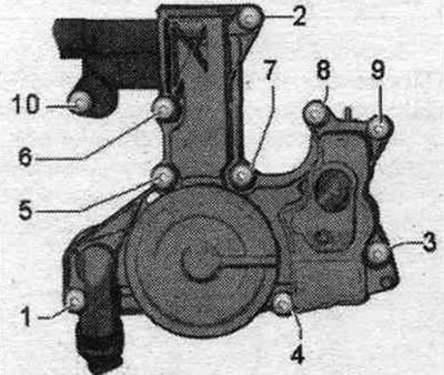
Tighten the system bolts. crankcase ventilation of the engine in sequence. "1...10" with a torque of 11 Nm.
Removal and installation the cylinder head
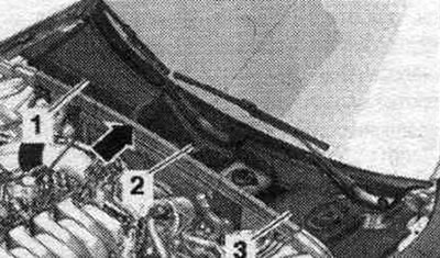
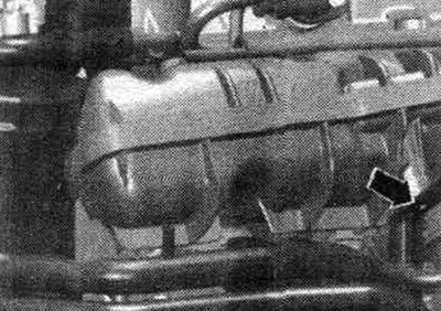
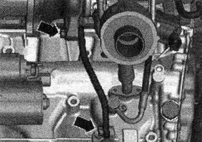
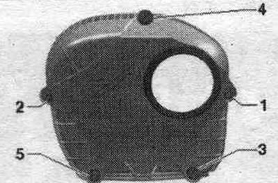
Free-running bolt camshafts have recesses in the camshafts. When reassembling, install all binders in the places where they were originally installed. Close the open channels of the intake circuit and system tightly. OG with corresponding plugs. For example, from the set of plugs for the "VAS 6122" engine, Remove the front noise insulation. Drain the coolant. Remove the exhaust pipe/front muffler. Remove the engine cover "arrows". Remove the water drainage box covers "1, 2, 3".
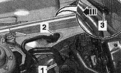
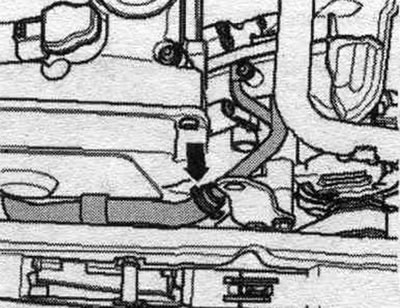
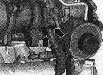
Remove the vacuum hose "2" from the end wall of the water deflector box; to do this, disconnect the vacuum hose "3" on the rear side "arrow". Remove the rear coolant hoses to the cylinder head.
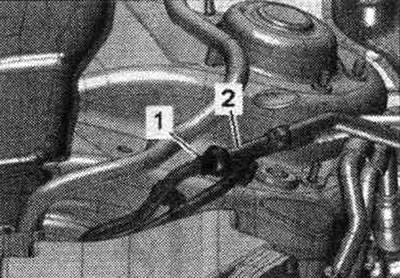
Disconnect the fuel. highways "1 and 2". Remove the front bumper cover and the bumper. Bring to service position.
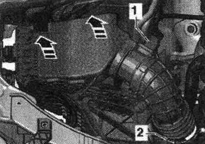
Disconnect connector "1" of air flow meter "G70". Release air intake pipe "2". Remove air flow meter housing. filter up "arrows".
Loosen the "arrow" hose clamps and remove the air duct hose.
Disconnect the following connectors.
2. Unfasten from knock sensor 1 "G61" and release; 3. From the intake manifold flap valve "N316", fuel pressure sensor "G247" and Hall sensor "G40"; 4. From the injectors; 5. From the throttle valve block -J338; 6. From the intake air temperature sensor "G42".
Disconnect connector "2" and release the wire.
Unscrew the coolant line bracket "arrow". For better visualization, the installation position is shown with the engine removed.
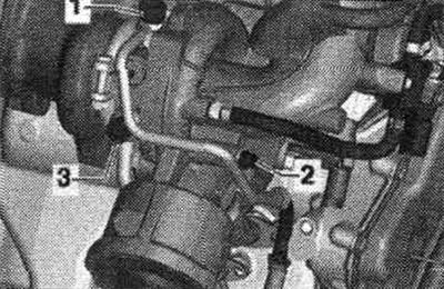
Remove the inlet pipe branch pipe by unscrewing the fastening nut "1" and bolt "2".
Disconnect the coolant hose "arrow".
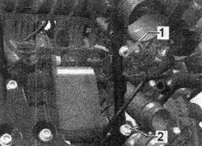
Unscrew bolts "1 and 2" and put the oil supply line aside. Unscrew bolt "3" and move the coolant line to the side.
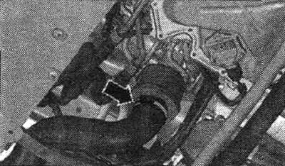
Disconnect the hose clamp "arrow", remove the air duct hose and set it aside.
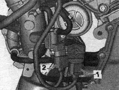
Disconnect connectors "1 and 4" from the oil pressure sensor "F22" and the low pressure oil pressure sensor "F378".
Disconnect connectors "1 and 2" and release the wire.
Unscrew the arrow bolts and remove the turbocharger support.
Unscrew the bolts "arrow" of the oil drain pipe.
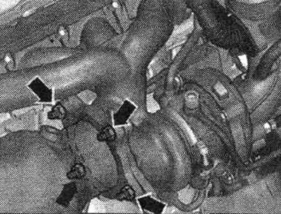
Unscrew the arrow nuts and move the catalytic converter back.
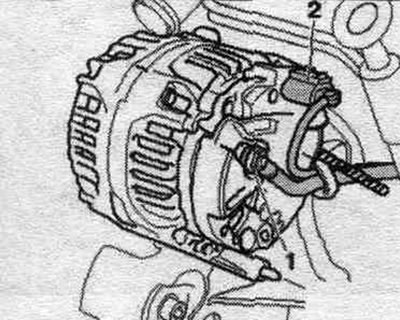
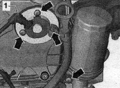
Disconnect the plug of the valve 1 of the variable valve timing system "N205" "1". Unscrew the bolts "arrows" and remove the valve 1 of the variable valve timing system "N205".
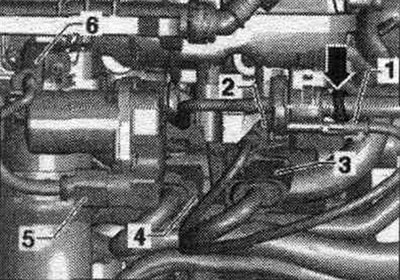
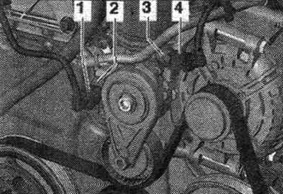
Remove bolts "1 through 5" and remove the upper timing chain cover. Remove the coil connector block bolts.
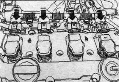
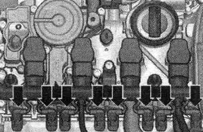
Unlock the "arrow" plugs and disconnect all the plugs from the coils at the same time.
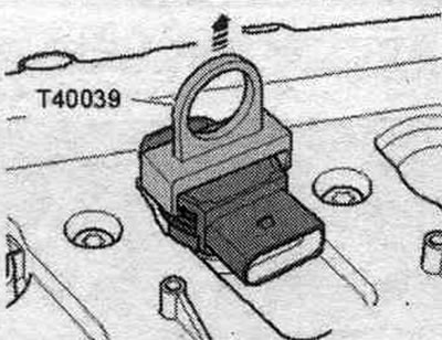
Remove the coils using the T40039 puller. Unscrew the spark plugs using the 3122 B spark plug wrench.
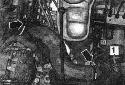
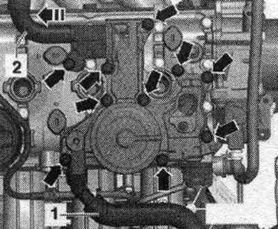
Disconnect the system hose. crankcase ventilation of the engine "1". Unscrew the bolts "arrows", remove the system. crankcase ventilation system and disconnect it from hose "2" of the engine crankcase ventilation system in the "direction of the arrow".
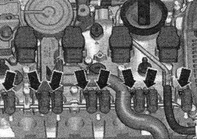
Remove the "arrow" connectors from the adjusting elements of the system. regulation of the timing phases.
Remove the adjusting elements of the system. "arrow" timing phase adjustment.
Turn the "arrow" plug counterclockwise in the "direction of the arrow" by 90° and remove. Unscrew the ball head "1...2". Remove the cover.
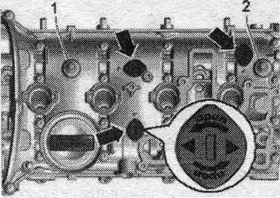
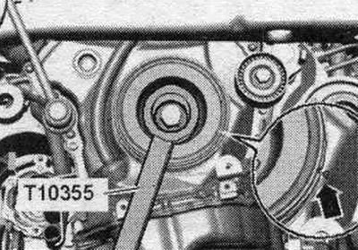
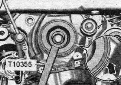
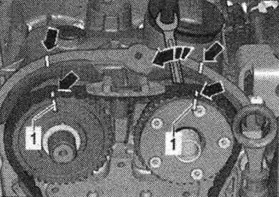
Rotate the vibration damper to the "TDC" position using the "T10355" counterholder. The notch on the vibration damper should be aligned with the arrow mark on the lower chain drive cover. The "1" marks on the camshafts must face upwards.
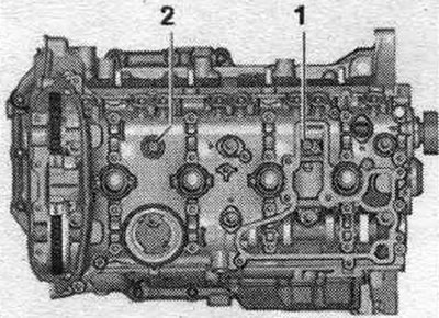
Unscrew cylinder head bolts "1 and 2".
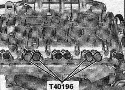
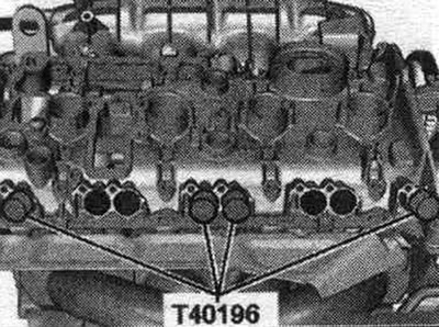
Mounting pins "T40196" must only be inserted in the positions shown. Insert mounting pins "T40196" as shown in the figure. Rotate the crankshaft 4 revolutions in the direction of engine rotation. Remove the mounting pins "T40196".
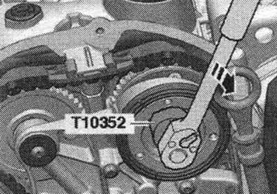
The distribution valve has a left-hand thread. Depending on the configuration, remove the distribution valve using the "T10352" puller or the "T10352/1" puller in the "direction of the arrow".
Unscrew the "arrow" bolts and remove the bearing housing.
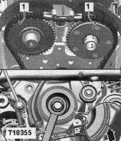
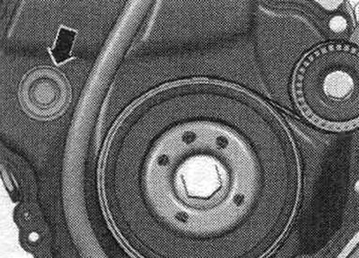
Turn the vibration damper with counter-support "T10355" to the "TDC" position "arrow". The notch on the vibration damper must be opposite the arrow mark on the lower timing chain cover.
Mark the camshaft drive chain and cylinder head "arrows" to the marks on the chain sprockets "1" with a waterproof marker.

Remove the "arrow" plug.
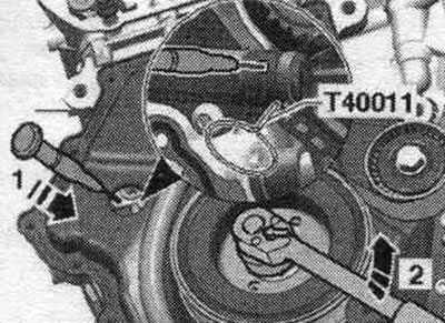
Raise the chain tensioner locking wedge by inserting a marking needle or a suitable screwdriver into the tensioner hole in the direction of arrow 1. Rotate the crankshaft counterclockwise in the direction of arrow 2 and secure it with pin T40011. The intake camshaft now rotates in the direction of engine rotation.
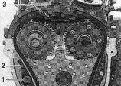
Remove bolt "1" and move tension bar "2" downward. Remove upper chain guide "3" by unlocking the locking mechanism with a screwdriver and pushing the guide forward. Remove the camshaft drive chain from the sprockets. Risk of damage to valves and piston crowns. If the camshaft drive chain is removed from the cylinder head, the crankshaft cannot be turned any further.
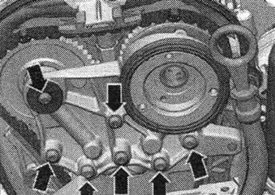
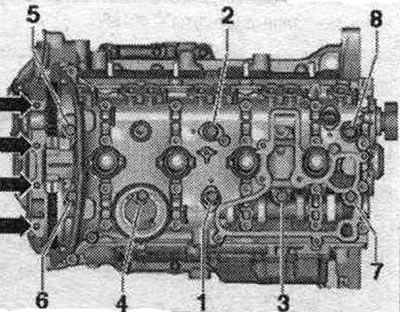
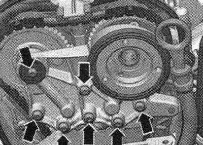
Unscrew the "arrow" bolts. Unscrew the cylinder head bolts in sequence. "1...8". To unscrew the cylinder head bolts, if necessary, turn the camshafts with a wrench. Check that all wires and cables are free! Pay attention to the tensioner bar and chain guide bar when lifting the cylinder head. Remove the cylinder head. Place the cylinder head on a soft pad (foam).
Installation
Caution! Risk of damage to the sealing surface. Carefully remove any remaining sealant from the cylinder head and cylinder block. Avoid creating long scratches or burrs. Risk of damage to the cylinder block. There should be no oil or coolant in the blind holes of the cylinder head bolts. Risk of a leaky cylinder head gasket. Carefully remove any remaining residue after sanding and grinding. The new cylinder head seal should be removed from the packaging immediately before installation. To prevent damage to the silicone layer and the grooves of the cylinder head gasket, handle the gasket with particular care. Risk of damage to open valves. When installing a replacement cylinder head, remove the plastic base to protect the exposed valves only when it comes into direct contact with the cylinder head. There is a risk of damage to the valves and piston crowns after working on the valve train. To ensure that no valves come into contact with the cylinder head during operation, carefully rotate the engine at least 2 revolutions. Replace any bolts that were over-tightened. Replace all seals, gaskets and self-locking nuts. Consider different sealants for cylinder head sealing surfaces and caps. Secure all hose connections with hose clamps of the appropriate series.
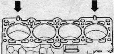
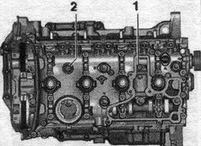
Install the cylinder head gasket. Take into account the centering pins in the cylinder block "arrows". Take into account the installation. position of the cylinder head gasket, marking: the part number must be clearly visible from the intake side.
Make sure that the timing chain does not damage other components when turning the crankshaft. If the crankshaft has been turned, bring the piston of the first cyl. at TDC and again slightly turn the crankshaft back. Install the cylinder head. To tighten the cylinder head bolts, turn the intake camshaft with a wrench. Insert bolts "1...8". Tighten the cylinder head bolts in sequence. "1...8" in 3 steps. Tighten the "arrow" bolts in 2 stages. Further tightening of the cylinder head mounting bolts is not necessary after repair work.
Turn the vibration damper with counter-support "T10355" to the "TDC" position "arrow". The notch on the vibration damper must be opposite the arrow mark on the lower timing chain cover. The marked camshaft timing chain links must be installed in accordance with the markings on the sprockets and cylinder head.
Turn the intake camshaft with a wrench in the direction of the arrow and put on the drive chain. The markings on the camshaft and cylinder head drive chain "arrows" must match the sprockets of the chain "1".
Place the bearing housing on the bearing and tighten the "arrow" bolts by hand. Remove the "T40011" locking pin. Tighten the "arrow" bolts of the bearing housing. Install the distribution valve.
Insert mounting pins "T40196" as shown in the figure. Rotate the crankshaft 4 revolutions in the direction of engine rotation. Remove the mounting pins "T40196".
Insert bolts "1 and 2". Tighten the cylinder head bolts in sequence. "1 and 2" in 3 steps.
Installation in reverse order. Change the oil. Install the upper drive chain cover. Replace the coolant. Install a catalytic converter. Install the downpipe/front muffler.
[The original source of the article can be found on the website «Audimanual.ru»]