Table of contents: Crankshaft - sequence, tightening… ↓ Pistons and connecting rods ↓ Mounting position of the bearing… ↓ Disconnect the new connecting rod ↓
Note: To perform installation work, the engine must be secured using the engine and gearbox holder - VAS 6095 - on the mounting stand.
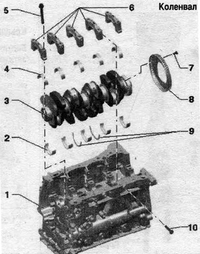
1. Cylinder block.
2. Bearing insert installed in the cylinder block: with lubrication groove; do not interchange previously used bearing shells (mark when removing).
3. Crankshaft: after removal, position it so that the sensor gear "pos. 5" does not touch it and cannot be damaged; when replacing the crankshaft, it is necessary to re-select the bearing shells in accordance with the bearing cap; when measuring the radial clearance, do not over-tighten the crankshaft.
4. Bearing insert installed in bearing cap: without lubrication groove; do not interchange previously used bearing shells (mark when removing).
5. Bolt: replace.
6. Bearing cover: Bearing cover 1: crankshaft pulley side; the retaining tabs of the bearing shells in the cylinder block and bearing caps must lie on top of each other.
7. Bolt: 10 Nm + 90° turn; replace; after each unscrewing of the bolts, replace the sensor gear.
8. Ring gear: for engine speed sensor "G28"; installation is possible only in one position "holes are offset"; after each unscrewing of the bolts, replace the sensor gear.
9. Adjusting washers: for bearing 3.
10. Bolt: replace.
Crankshaft - sequence, tightening torques
Tighten the crankshaft bolts in sequence. "1...5" as follows.
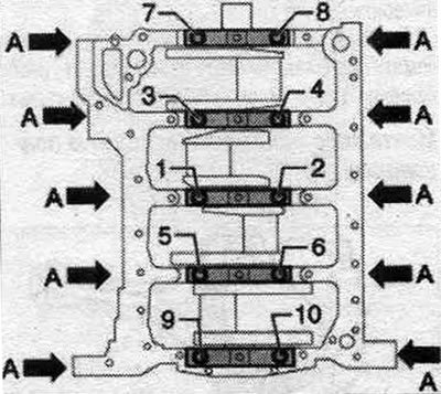
1. Screw in bolts "1...10" and "arrows" by hand; 2. Pre-tighten bolts "1...10" to a torque of 65 Nm; 3. Tighten bolts "1...10" by 90° using a rigid wrench; 4. Pre-tighten the arrow bolts to a torque of 20 Nm; 5. Tighten the arrow bolts with a hard wrench by 90°.
Crankshaft bearing alignment (classification)
At the factory, bearing liners of the required thickness are selected for the cylinder block. Colored marks are used to indicate the thickness of the bearing shells. Information on which bearing should be installed where in the cylinder block (upper bearing shell), indicated on the lower surface of the seal and on the end face of the cylinder block using letter markings. Information on which bearing should be installed where in the bearing cap (lower bearing shell), indicated on the crankshaft using letter markings. The first letter corresponds to the first bearing cap, the second to 2, etc.
Designation of cylinder block bearing shells
The cylinder block marking may be located on the oil seal surface. pallet or on the end wall (from the KP side) cylinder block.
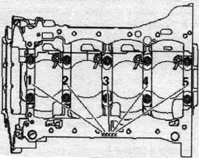
The cylinder block marking indicates the conformity of the upper bearing shells (bearing shell from the cylinder block side). Write down the letter and determine from the table the color marking of the insert to be installed.
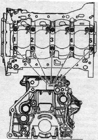
Bearing shell designation on the cover
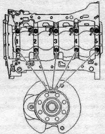
The crankshaft marking indicates the conformity of the lower bearing shells (bearing shell from the bearing cap side). Write down the letter and determine from the table the color marking of the insert to be installed.
| S = | black |
| R = | red |
| G = | yellow |
| B = | blue |
| W = | white |
Crankshaft dimensions (dimensions in mm)
| Grinding size (1) | Crankshaft bearing, journal diameter | Connecting rod bearing, journal diameter |
| Basic size | 58,00 | 47,80 |
(1) Treatment of worn crankshafts is not provided.
Pistons and connecting rods
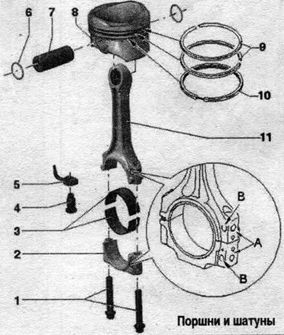
1. Connecting rod cap mounting bolt: on a 1.8 L engine: 30 Nm + turn an additional 90°; on a 2.0 L engine: 45 Nm + turn 90°; replace; lubricate the threads and mating surface with oil; use old bolts to check radial runout; to measure the radial clearance, tighten to 30 Nm, but do not tighten further.
2. Connecting rod cap: install in the proper position; thanks to the connecting rods, which are constructed using the method of constructive breaking (cracking), the connecting rod cap is installed in only one position and only on the corresponding connecting rod; mark belonging to cylinder "A"; location: "B" marks facing the pulley.
3. Bearing liners: Do not interchange previously used bearing liners (mark when removing); axial displacement of a new part: 0.10...0.35 mm; tolerance limit: 0.40 mm; radial runout measured with Plastigage: new: 0.02...0.06 mm, wear tolerance limit: 0.09 mm; when measuring radial runout, do not turn the crankshaft.
4. Safety valve: 27 Nm.
5. Oil nozzle: for cooling pistons.
6. Retaining ring: replace.
7. Piston pin.
8. Piston: mark installation. position and correspondence to the cylinder; the arrow on the bottom of the piston points towards the belt pulley.
9. Compression rings: remove and install using piston ring pliers; place the locks at a 120° offset; installation position: the "TOP" mark or the inscribed side faces the piston bottom.
10. Oil scraper ring: 2-piece; install the upper ring lock with an offset of 120° relative to the adjacent compression ring; the "TOP" or "R" mark should be directed towards the piston bottom; before installation, separate the locks of the oil scraper ring tape rings relative to each other; the height gap cannot be measured.
11. Connecting rod: replace only the entire set; mark belonging to cylinder "A"; location: "B" marks facing the pulley.
Mounting position of the bearing shell
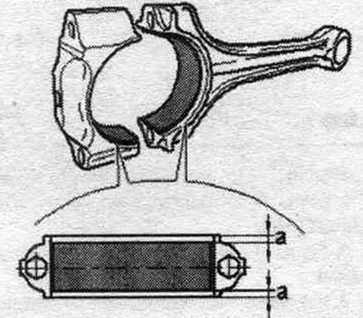
Place the bearing shells coaxially into the connecting rod and connecting rod cap. The size "a" must be the same on the left and right.
Disconnect the new connecting rod
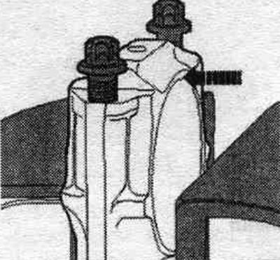
On new connecting rods it may turn out that the forced fracture point is not completely broken. Do not remove the connecting rod cap by hand, proceed according to the following instructions. Mark the alignment of cylinders and connecting rods. Apply light tension to the connecting rod as shown in the illustration using a vice with protective jaw pads. The connecting rod tension should not be too strong to avoid damage. The connecting rod drops below the dotted line. Loosen both arrow bolts by approximately 5 turns.
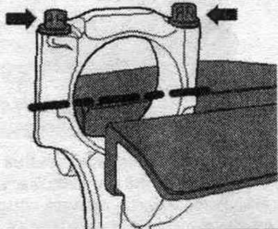
Gently tap the cap several times with a plastic hammer in the "direction of the arrow" away from the connecting rod cap until the cap is loosened.