
Repair Chevrolet Repair Toyota Repair Honda Repair AvtoVAZ Repair Mercedes-Benz Repair BMW Repair Opel
Home  |  Contacts  |  Sitemap  |    
English Русский
Български
Беларускі
Український
Српски
Hrvatski
Română
Polski
Slovenský
Magyar
AudiManual.ru


  • AUDI 80
  • AUDI 100
  • AUDI A3
  • AUDI A4
  • AUDI A6
  • AUDI A8
  • AUDI Q
  • OTHER
  • ARTICLES
B8 (2007-2015) B7 (2004-2008) B6 (2000-2006) B6 (2000-2006, petrol) B5 (1994-2001) B5 (1994-2001, petrol)

Cylinder block from the belt pulley side (Audi A4 B8)

  • Home
  • Audi A4
  • B8 (2007-2015)
  • Power unit
  • Petrol engines 1.8/2.0 l
  • Cylinder block from the belt pulley side
            0
Table of contents: Poly V-belt drive, additional… ↓ Auxiliary Holder Bolt Tightening… ↓ Poly V-belt running ↓ Removal and installation the… ↓ Removal and installation the… ↓

Poly V-belt drive, additional bracket. units
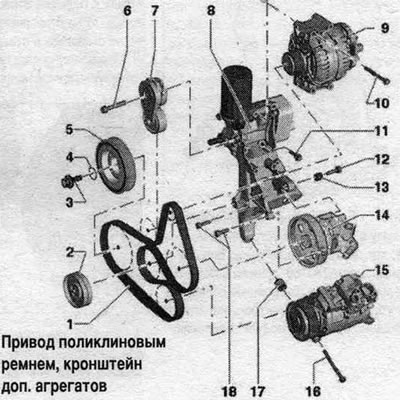


1. Poly V-belt: check for wear, do not bend; when installing, ensure correct position on the…

1. Poly V-belt: check for wear, do not bend; when installing, ensure correct position on the pulleys.
2. Intermediate roller; 20 Nm.
3. Bolt: replace; lubricate the seal with oil. ring; 150 Nm + 90° rotation; use the T10355 counterstop for loosening and tightening. To avoid adjusting the timing, do not turn the crankshaft while the bolt is removed.
4. Sealing ring: not a spare part, included in the bolt delivery scope.
5. Torsional vibration damper: with poly V-belt pulley. To avoid changing the timing phases, do not turn the crankshaft from the TDC position with the damper removed.
6. Bolt: 40 Nm.
7. Poly V-belt tensioner: To relieve the poly V-belt, move it back using a wrench; secure with the "T40098" clamp.
8. Additional holder. units: with oil filter and oil radiator.
9. Generator.
10-12. Bolt.
13. Bushing.
14. Vane pump.
15. Air conditioning compressor: do not unscrew/disconnect the refrigerant lines.
16. Bolt.
17. Compressor mounting sleeve.
18. Bolt.


Auxiliary Holder Bolt Tightening Sequence. units


Install additional holder. units and first screw in bolt "4", Tighten the bolts in sequence. "1...5" in 3 stages as follows.
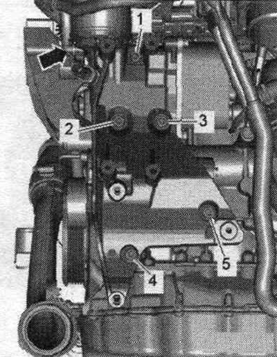
1. Tighten the bolts by hand; 2. Tighten the bolts to a torque of 20 Nm; 3. Tighten the bolts by…

1. Tighten the bolts by hand; 2. Tighten the bolts to a torque of 20 Nm; 3. Tighten the bolts by 90°.


Poly V-belt running
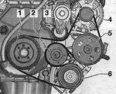


1. Torsional vibration damper; 2. Intermediate roller; 3. Poly V-belt tensioner; 4. Generator; 5.…

1. Torsional vibration damper; 2. Intermediate roller; 3. Poly V-belt tensioner; 4. Generator; 5. Vane pump; 6. Air conditioning compressor.


Removal


To reinstall the poly V-belt, mark the direction of rotation with chalk or a felt-tip pen before removing it. To loosen the poly V-belt, turn the tensioner in the direction of the arrow. Secure the tensioner with the T40098 clamp. Remove the poly V-belt.
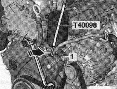
To reinstall the poly V-belt, mark the direction of rotation with chalk or a felt-tip pen before…


Installation


Installation in reverse order. Before installing the poly V-belt, the generator and compressor must be installed. Install the poly V-belt as shown in the figure. Turn the tensioner in the direction of the arrow and remove the locking pin "T40098". Loosen the tensioner. Check that the poly V-belt is installed correctly. Start the engine and check that the poly V-belt runs correctly.


Removal and installation the additional holder. units


Drain the coolant. To loosen the poly V-belt, turn the tensioner in the direction of the arrow. Secure the tensioner with the T40098 clamp. Remove the poly V-belt. Unscrew bolt "1" and remove the poly V-belt tensioner from the additional holder. units. Place a rag under the auxiliary holder. units to collect leaking oil. Disconnect connectors "1 and 4" from the oil pressure sensor "F22" and the low pressure oil pressure sensor "F378".
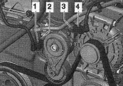
Drain the coolant. To loosen the poly V-belt, turn the tensioner in the direction of the arrow.…


Loosen the "arrow" hose clamps and remove the air duct hose. Remove the generator.
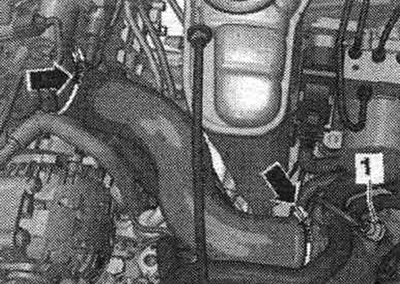
Loosen the «arrow» hose clamps and remove the air duct hose. Remove the generator.


Disconnect plug connection "1" of the electromagnetic clutch on the compressor. Unscrew the compressor "arrow" bolts.
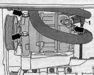
Disconnect plug connection «1» of the electromagnetic clutch on the compressor. Unscrew the…


Tie the compressor with the refrigerant hoses connected to the side member from above. The hydraulic lines of the general purpose pump remain connected. Remove bolts "1" through the belt pulley at the front, and bolt "2" from the rear. The illustration shows the general purpose water pump without a belt pulley and without hydraulic lines. Place the hydraulic pump with the connected hydraulics. lines on the spar.


Tie the compressor with the refrigerant hoses connected to the side member from above. The…


Loosen the oil filter "arrow" using the key "3417" and remove it.
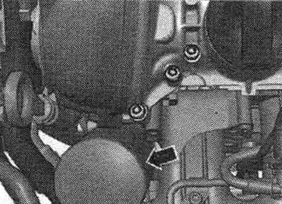
Loosen the oil filter «arrow» using the key «3417» and remove it.


Unscrew the "arrow" bolt of the oil dipstick guide tube. Unscrew bolts "1...5" and remove the additional holder. units from the coolant pump housing.
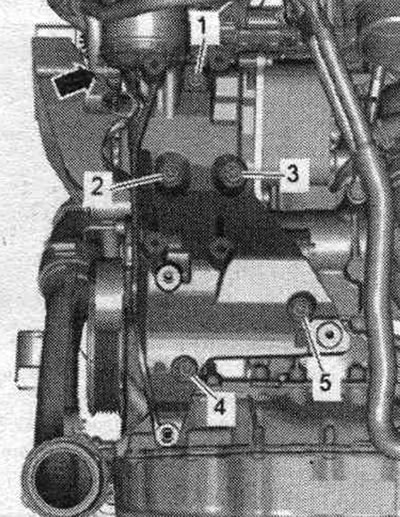
Unscrew the «arrow» bolt of the oil dipstick guide tube. Unscrew bolts «1...5» and remove the…


Installation


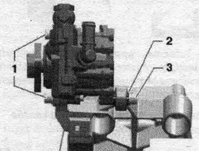
Installation in reverse order. Replace bolts that were tightened with additional tightening. Replace gaskets and seals. o-rings. Wet the seal. o-rings "4" concentrate. Insert the connecting pipe "2" into the housing "3" of the coolant pump. Push on the auxiliary bracket. units "1" on the connecting pipe, insert the bolts and tighten.
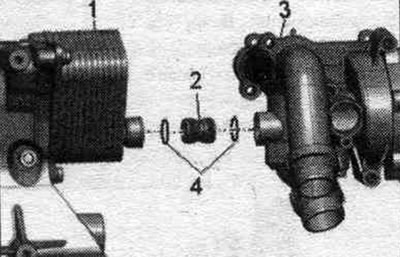


Installation in reverse order. Replace bolts that were tightened with additional tightening.…


Install a vane pump. Install the compressor. Install the generator. Install the poly V-belt. Fill with coolant. Check the oil level.

Removal and installation the vibration damper


Remove the front sound insulation. Remove the plug connection "1" of the radiator fan from the mount by moving the lock back "arrow" and pressing the stopper down. Release the radiator fan control unit wire harness.
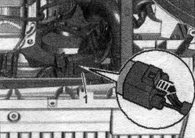
Remove the front sound insulation. Remove the plug connection «1» of the radiator fan from the…


Disconnect plug connections "2" and "3". Unscrew bolt "arrow" and remove control unit "1" of the radiator fan.
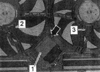
Disconnect plug connections «2» and «3». Unscrew bolt «arrow» and remove control unit «1» of the…


To loosen the poly V-belt, turn the tensioner in the direction of the arrow. Secure the tensioner with the T40098 clamp. Remove the belt from the poly V-belt pulley.
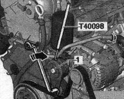


To loosen the poly V-belt, turn the tensioner in the direction of the arrow. Secure the tensioner…


Turn the torsional vibration damper with support "T10355" to the "TDC" position "arrow". The notch on the vibration damper must be opposite the arrow mark on the lower timing chain cover. Remove the damper bolt using the T10355 counter support. To avoid altering the timing, do not rotate the crankshaft past the TDC position with the damper removed.
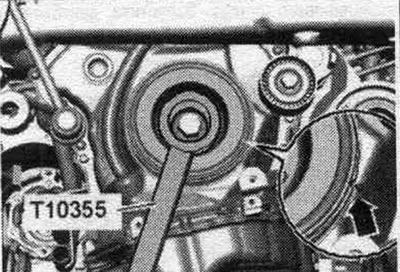
Turn the torsional vibration damper with support «T10355» to the «TDC» position «arrow». The notch…


Installation


Installation in reverse order. Replace the vibration damper bolt. Replace the seal. o-ring "1". Lubricate the shaft seal lip with oil. Fit the vibration damper, taking into account the contour of the "arrow" teeth.
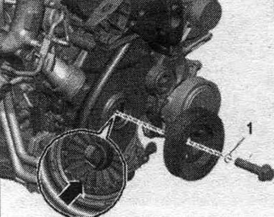
Installation in reverse order. Replace the vibration damper bolt. Replace the seal. o-ring «1».…


Install the poly V-belt. Install the radiator fan control unit "J293".
The article was checked by auto expert Timur Bazhenov
This article is available at russian, bulgarian, belarusian, ukrainian, serbian, croatian, romanian, polish, slovak, hungarian

Share information:
Previous articles
Audi A4 B8: Petrol engines 1.8/2.0 l
Next articles

1.8/2.0L Engines — Removal and Installation
Characteristics of 1.8/2.0 L engines
Cylinder block from the gearbox side
Crankshaft — removal and installation
Timing Chain Covers — Removal and Installation
Chain drive — removal and installation


Similar articles on other Audi car models:
Technical characteristics of the cylinder block Audi 80 B2 (1979-1986)
Cylinder block/crankcase — cleaning and inspection Audi 100 C3 (1982-1990, diesel)
Checking the timing belt for damage, measuring wear Audi A3 Type 8L (1996-2003)
Replacing the drive belt (4-cylinder engines) Audi A6 C4 (1994-1997)
Checking the condition of the poly V-belt Audi A8 D2 (1994-2002)
Cylinder block from the belt pulley side Audi Q5 Type 8R (2008-2017)
Replacing the crankshaft seal on the belt pulley side Audi A2 (1999-2005)
Link to this page in different formats


Visitor comments

No comments yet


How much will 12 + 17 =


A4(B8, 2007-2015) 
  • General information
  • Operating instructions
  • Power unit
  • Petrol engines 1.8 l
  • Petrol engines 1.8/2.0 l
  • Petrol engines 3.0 l
  • Petrol engines 3.2 l
  • Fuel system (petrol)
  • Diesel engines 2.0 l (CA*)
  • Diesel engines 2.0 l (CJCB)
  • Diesel engines 2.7/3.0 l
  • Diesel engines 3.0 l
  • Fuel system (diesel)
  • Transmission
  • Manual gearbox 0B1
  • Manual gearbox 0B2
  • Manual gearbox 0B3
  • Manual gearbox 0B4
  • Automatic transmission 0B5
  • Automatic transmission 0B6
  • Automatic transmission 0AW
  • All-wheel drive system
  • Chassis
  • Front suspension
  • Rear suspension
  • Brake system
  • Steering system
  • Body
  • Exterior
  • Interior
  • Seats
  • Doors, locks and windows
  • Security system
  • Heating and air conditioning
  • Electrical equipment
  • Audio system
  • Power devices
  • Equipment and devices
  • Lighting and lamps
  • Electrical circuits
 
A4(B7, 2004-2008) 
  • General information
  • Introduction to manual
  • Troubleshooting
  • Operating instructions
  • Maintenance
  • Power unit
  • Petrol engines 2.0 (ALT)
  • Petrol engines 2.0 (TFSI)
  • Petrol engines 1.8 (MPI)
  • Diesel engines
  • Cooling system
  • Air conditioner
  • Fuel and exhaust system
  • Ignition system
  • Starting and charging
  • Transmission
  • Clutch
  • Manual gearbox
  • Automatic gearbox
  • Drive shafts
  • Chassis
  • Brake system
  • Front suspension
  • Rear suspension
  • Steering
  • Body
  • Exterior
  • Interior
  • Electrical equipment
  • Equipment and devices
  • Lighting and signaling
  • Windscreen wipers and washers
  • Electrical diagrams
  • Electrical diagrams (since 2007)
 
A4(B6, 2000-2006) 
  • General information
  • Vehicle Description
  • User manual
  • Maintenance
  • Power unit
  • Gasoline engine
  • Diesel engine
  • Lubrication system
  • Cooling system
  • Supply system
  • Injection system
  • Exhaust system
  • Ignition and control
  • Transmission
  • Gear box
  • Clutch and drive shafts
  • Chassis
  • Brake system
  • Car suspension
  • Steering
  • Body
  • Heating and ventilation
  • Exterior (external elements)
  • Interior (internal elements)
  • Electrical equipment
  • Power devices
  • Lighting and appliances
  • Electrical circuits
 
A4(B6, 2000-2006, petrol) 
  • General information
  • Introduction to the guide
  • Car care
  • Power unit
  • Engine repair
  • Lubrication system
  • Cooling system
  • Injection and control system
  • Ignition system
  • Power and exhaust system
  • Transmission
  • Clutch and drive shafts
  • Car gearbox
  • Chassis
  • Suspension and wheels
  • Steering
  • Brake system
  • Body
  • Interior
  • Exterior
  • Electrical equipment
  • Equipment and devices
  • Lighting and signaling
  • Power devices
  • Electrical circuits
 
A4(B5, 1994-2001) 
  • General information
  • Introduction to the guide
  • Car care
  • Maintenance (gasoline)
  • Maintenance (diesel)
  • Power unit
  • Gasoline engines
  • Diesel engines
  • Engine overhaul
  • Cooling system
  • Fuel injection (gasoline)
  • Fuel system (diesel)
  • Exhaust system
  • Ignition system
  • Transmission
  • Clutch
  • Mechanical gearbox
  • Automatic gearbox
  • Drive shafts
  • Chassis
  • Brake system
  • Car suspension
  • Steering
  • Body
  • Exterior
  • Interior
  • Doors, locks and windows
  • Heating and ventilation
  • Electrical equipment
  • Power devices
  • Equipment and devices
  • Electrical circuits
 
A4(B5, 1994-2001, petrol) 
  • General information
  • Vehicle description
  • Maintenance
  • Power unit
  • Engine repair
  • Turbocharging
  • Exhaust system
  • Cooling system
  • Ignition system
  • Fuel system
  • Motronic injection system
  • MPI and MPFI injection system
  • Transmission
  • Clutch
  • Gearbox and shafts
  • Chassis
  • Steering
  • Car suspension
  • Brake system
  • Wheels and tires
  • Body
  • Heating and ventilation
  • Body parts
  • Electrical equipment
  • Fuses and relays
  • Power devices
  • Lighting and lamps
  • Tools and devices
  • Electrical circuits
 
AudiManual.ru © 2017-2026 · Mobile version · Feedback · Sitemap: EN BG BY UA RS HR RO PL SK HU · Site search · News and articles
80 B2 · 80 B3 petrol · 80 B3 · 80 B4 · 100 C3 diesel · 100 C3 petrol · 100 C3 · 100 C4 petrol · 100 C4 · A3 Type 8L · A4 B5 petrol · A4 B5 · A4 B6 petrol · A4 B6 · A4 B7 · A4 B8 · A6 C4 · A6 C5 · A6 C5 Allroad · A8 D2 · Q5 Type 8R · Q7 Typ 4L · Audi A2 ·
This site uses cookies 🍪. Click the button to accept this fact.