
Table of contents: Camshaft chain drive ↓ Crankshaft sprocket - mounting… ↓ Removal and installation the… ↓ Balance shaft drive chain ↓ Balance shaft tube - mounting… ↓ Support pin - mounting position ↓ Intermediate shaft gear - tightening… ↓ Removal and installation the balance… ↓ Replacing the intake camshaft… ↓ Replacing the exhaust camshaft… ↓ Checking the timing phases ↓
Camshaft chain drive
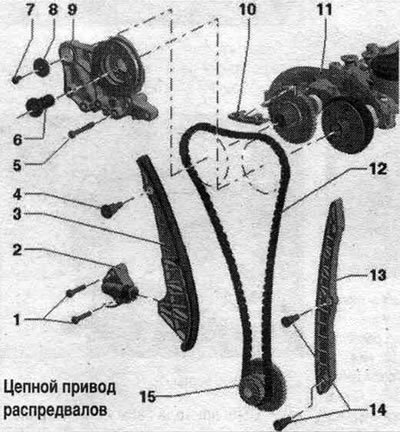
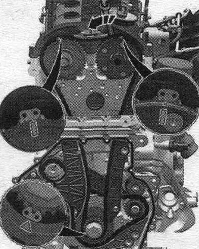
1. Bolt: 9 Nm. 2. Chain tensioner: spring-loaded; before removing, secure with the "T40011" insert pin. 3. Tension bar for the drive chain. 4. Guide bolt: 20 Nm. 5. Bolt: 9 Nm. 6. Distribution valve: left-hand thread; 35 Nm; depending on the configuration, remove using the puller "T10352" or the puller "T10352/1". 7. Bolt: replace; for 1.8 l: 8 Nm + turn 90°; for 2.0 l: 20 Nm + turn further by 90°. 8. Washer. 9. Crankshaft support ramp. 10. Timing chain guide bar. 11. Camshaft housing. 12. Camshaft chain: Before removing, mark the direction of rotation with paint. 13. Timing chain guide bar. 14. Guide bolt: 20 Nm. 15. Sprocket: crankshaft.
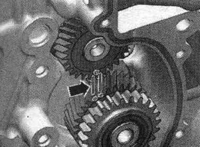
Crankshaft sprocket - mounting position
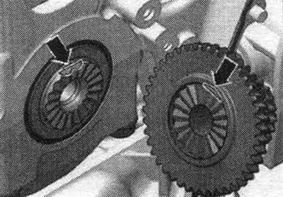
Both surfaces of the "arrow" must be located opposite each other.
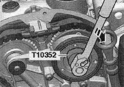
Removal and installation the camshaft chain drive
Remove the front bumper trim and bumper. Bring to service position. Remove the upper timing chain cover. The distribution valve has a left-hand thread. Depending on the configuration, remove using the puller "T10352" or the puller "T10352/1" in the "direction of the arrow".
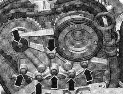
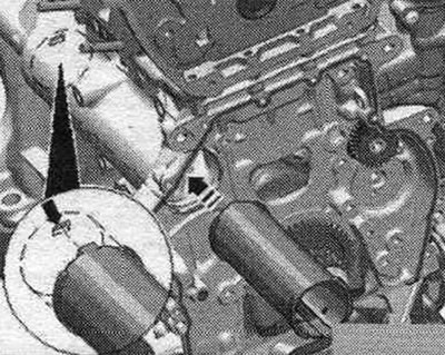
Unscrew the "arrow" bolts and remove the bearing housing.
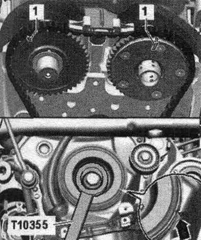
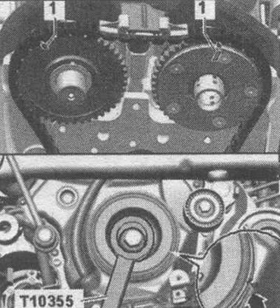
Turn the vibration damper with counter-support "T10355" to the "TDC" position "arrow". The notch on the vibration damper must be opposite the arrow mark on the lower timing chain cover. The "1" marks on the camshafts must face upwards. Remove the lower chain drive cover.
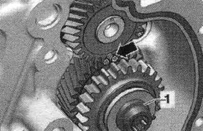
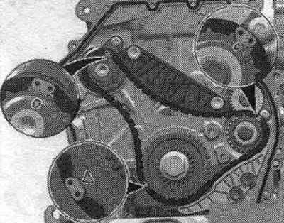
Press in the oil chain tensioner. pump in the "direction of the arrow" and secure with the locking pin "T40011". Remove the oil chain tensioner. pump "1". Remove the oil drive chain. pump.
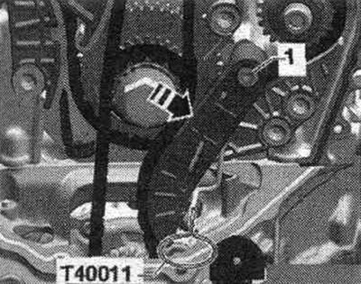
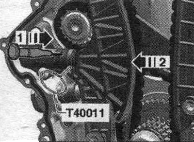
Raise the chain tensioner locking wedge by inserting a marking needle or a suitable screwdriver into the tensioner hole in the direction of arrow 1. Press the timing chain tensioner bar in the direction of arrow 2 and secure it with pin T40011. Remove the timing chain from the cylinder head. The intake camshaft will rotate in the direction of engine rotation.
Remove the chain drive tensioner bar "2". Remove the camshaft chain drive damper bar "1". Remove the drive chain.
Installation
The following tasks must be completed simultaneously. This requires the assistance of a second mechanic. The colored timing chain links should be installed according to the markings on the sprockets. Hold the key until the tension bar is installed. Place the drive chain on the exhaust camshaft. Place the drive chain on the crankshaft. Turn the intake camshaft with a wrench in the direction of the arrow and put on the drive chain.
Install the timing chain tensioner and tighten bolt "2". Install the camshaft timing chain guide and tighten bolts "1". Install the bearing housing and tighten the bolts "arrows" by hand. Remove the locking pin "T40011". Tighten the bearing housing bolts "arrows". Install the distribution valve. Installation in reverse order. Install the lower chain drive cover. Install the upper drive chain cover. Install the tensioner for the poly V-belt. Install the poly V-belt. Return to service position. Install the front bumper cover and bumper.
Balance shaft drive chain
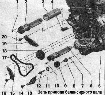
1. Bolt: Replace: 9 Nm. 2. Balance shaft: exhaust side; must be replaced after removal; lubricate the support with oil; replace. 3. Balance shaft tube. 4. Chain tensioner: 65 Nm. 5. Cylinder block. 6. Balance shaft: intake side; must be replaced after removal; lubricate the support with oil; replace. 7. Sealing ring: lubricate with oil. 8. Support pin: lubricate with oil. 9. Balance shaft intermediate shaft gear; if the bolt has come loose, replace the intermediate shaft gear. 10. Bolt: replace; 9 Nm. 11. Washer. 12. Bolt: If the bolt has come loose, replace the intermediate shaft gear. 13. Idler bar: for timing chain. 14. Guide bolt: 20 Nm. 15. Tensioner bar: for timing chain. 16. Guide bolt: 20 Nm. 17. Timing chain. 18. Sprocket. 19. Idler bar: for balance shaft drive chain. 20. Guide bolt: 20 Nm.
Balance shaft tube - mounting position
The balance shaft tube journal must be fixed in the "arrow" groove.
Support pin - mounting position
Replace and lubricate the seal. ring "1". The mounting pin "arrow" of the support pin must enter the hole in the cylinder block. Lubricate the support pin.
Intermediate shaft gear - tightening sequence
The intermediate shaft gear must be replaced. Otherwise, the tooth profile clearance will not be adjusted, which will lead to engine damage. The new intermediate shaft gear has a varnish coating that wears off quickly, thereby automatically creating a gap in the tooth profile. Tighten the new bolt in the following order.
1. Pre-tighten to 10 Nm; 2. Rotate the intermediate shaft gear. The intermediate shaft gear should not have any play, otherwise loosen and tighten again; 3. Tighten to 25 Nm; 4. Tighten 90° further with a regular wrench.
Removal and installation the balance shaft chain drive
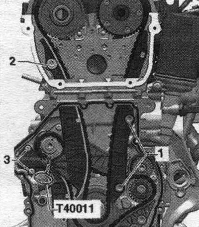
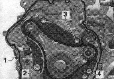
Remove the upper timing chain cover. Remove the lower chain drive cover. Remove the camshaft chain drive. Remove the camshaft chain guide rail "1". Remove the camshaft chain tensioner "3".
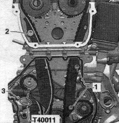
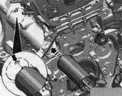
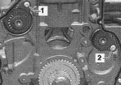
Remove balance shaft drive chain tensioner "1". Remove tension bar "2". Remove damper "3". Remove damper "4". Remove drive chain.
Installation
Rotate the intermediate shaft sprocket/balance shaft to the "arrow" markings. The colored timing chain links should be installed according to the markings on the sprockets.
Install the timing chain, the colored links of the timing chain must be installed according to the markings on the sprockets.
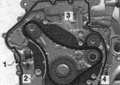
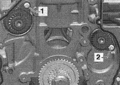
Install the drive chain tensioner and tighten bolts "4". Install the drive chain tensioner and tighten bolts "3". Install the drive chain tensioner bar and tighten bolt "2". Install the chain tensioner "1" using thread locking compound.
Check the adjustment again. Check the markings on the intermediate shaft/balance shaft sprocket "arrows". For greater clarity, the intermediate shaft/balance shaft marking is shown with the chain removed. Installation in reverse order. Install the camshaft chain. Install the lower chain drive cover. Install the upper drive chain cover. Install the tensioner for the poly V-belt. Install the poly V-belt.
Replacing the intake camshaft balance shaft
The intake camshaft balance shaft must be replaced after removal. Remove the timing belt from the system pump. cooling. Remove the upper timing chain cover. Remove the lower chain drive cover. Remove the camshaft chain drive. Remove the balance shaft drive chain. Remove intermediate shaft sprocket "1".
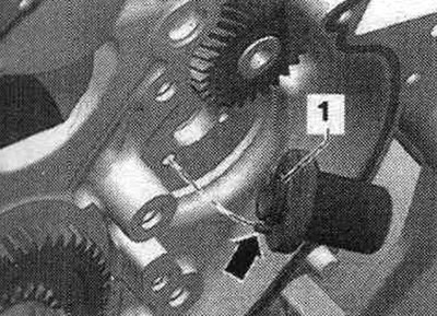
Unscrew bolt "2" of the intake camshaft balance shaft.
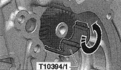
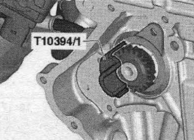
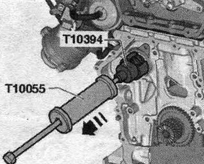
Install the "T10394/1" cup of the "T10394" puller and turn it upwards in the direction of the arrow.
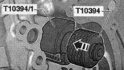
Install the puller "T10394" and move the sliding sleeve in the "direction of the arrow".
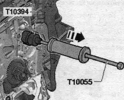
Screw the puller "T10055" into the puller "T10394" and press out the balance shaft in the "direction of the arrow".
Installation
Due to the small clearance between the balance shaft and the cylinder block, the balance shaft should be installed as cold as possible! Make sure the balance shaft can be inserted into the cylinder block. without effort. Otherwise, the balance shaft must be installed in an unheated state. Place the new balance shaft in the refrigerator for 30 minutes or spray it with a standard cooling spray. Lubricate the balance shaft support with oil. Install a new intake camshaft balance shaft and tighten bolt "2". Replace and lubricate the seal with oil. ring "1". Lubricate the support pin with oil and insert it, the mounting pin "arrow" of the support pin must be inserted into the hole in the cylinder block. The intermediate shaft gear must be replaced. Otherwise, the tooth profile clearance will not be adjusted, which will lead to engine damage. The new intermediate shaft gear is coated with a varnish for lubrication, this coating wears off quickly, providing automatic adjustment of the tooth profile clearance.
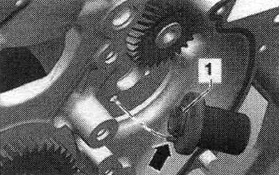
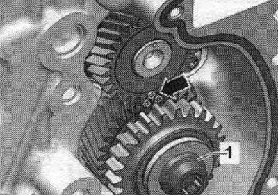
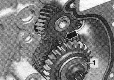
Apply "arrow" paint to the intermediate shaft sprocket tooth profile. Insert the intermediate shaft sprocket; the marking on the balance shaft should be between the marks on the tooth profile.
Tighten the intermediate shaft sprocket bolt "1": sequence, tightening. Check the markings on the intermediate shaft/balance shaft sprocket "arrows". Installation is in the reverse order. Install the balance shaft drive chain. Install the camshaft chain. Install the lower chain drive cover. Install the upper drive chain cover. Install the tensioner for the poly V-belt. Install the poly V-belt. Replacing the sealing cuff of the drive shaft of the system pump. cooling. Install the toothed belt of the system pump. cooling.
Replacing the exhaust camshaft balance shaft
The exhaust camshaft balance shaft must be replaced after removal. Remove the upper timing chain cover. Remove the lower chain drive cover. Remove the camshaft chain drive. Remove the balance shaft drive chain. Unscrew bolt "1" of the exhaust camshaft balance shaft.
Install the "T10394/1" cup of the "T10394" puller.
Install the puller "T10394" and move the sliding sleeve in the "direction of the arrow".
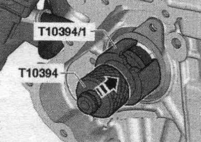
Screw the puller "T10055" into the puller "T10394" and press out the balance shaft.
Installation
Due to the small clearance between the balance shaft and the cylinder block, the balance shaft should be installed as cold as possible! Make sure the balance shaft can be inserted into the cylinder block. without effort. Otherwise, the balance shaft must be installed in an unheated state. Check the installation. balance shaft tube position "arrow." The "arrow" journal should fit into the groove. Place the new balance shaft in the refrigerator for 30 minutes or spray it with a standard cooling spray. Lubricate the balance shaft support with oil.
Install a new exhaust camshaft balance shaft. Before tightening bolt "1", make sure that the balance shaft fits tightly against the engine crankcase. If the balance shaft does not fit tightly, the balance shaft tube must be replaced. Installation in reverse order. Install the balance shaft drive chain. Install the camshaft chain. Install the lower chain drive cover. Install the upper drive chain cover. Install the tensioner for the poly V-belt. Install the poly V-belt.
Checking the timing phases
Remove the top chain drive cover. Remove sound insulation. Turn the vibration damper from below, in the direction of engine rotation, to the "TDC" position "arrow". To turn the vibration damper, use a ratchet with a 24 mm socket. Set the vibration damper in the direction of engine rotation to "TDC". Do not correct the TDC position by turning in the opposite direction! The notch on the vibration damper must be opposite the arrow mark on the lower timing chain cover (use a mirror). The "1" marks on the camshafts must face upwards.
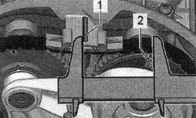
Measure the distance from the outer edge of jumper "1" to mark "2" on the intake camshaft. Mandatory value: 61...64 mm.
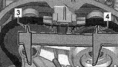
When the specified value is reached, measure the distance between mark "3" on the intake camshaft and mark "4" on the exhaust camshaft. The specified value is 124-126 mm. A one-tooth offset results in a deviation from the specified value of approximately 6 mm. If any offset is detected, the timing chain must be reinstalled.
(The original version is on the portal «AUDIMANUAL.ru»)