
Table of contents: Disconnecting the cylinder head ↓ Cylinder head bolt tightening… ↓ Removal and installation the… ↓ Compression check ↓
Note: Replace the cylinder head mounting bolts. When performing installation work, replace the self-locking nuts, bolts that require additional tightening, and seals. rings and seals. The plastic linings included in the repair kit for protecting exposed valves may be removed immediately before installing the cylinder head. If the cylinder head or head gasket was replaced, the coolant and oil must be changed.
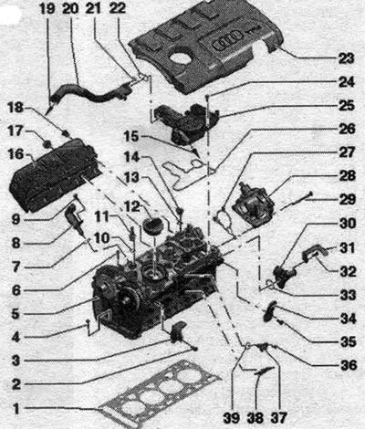
1. Cylinder head seal: replace; take into account mont. position: cylinder head part number. 2. Bolt: 25 Nm. 3. Transport eye. 4. Bolt: replace; take into account the sequence of actions when unscrewing; follow the correct procedure when tightening. 5. Cylinder head. 6. Cylinder head bolt: replace; take into account the sequence of actions when unscrewing; follow the correct procedure when tightening. 7. Sealing ring: replace, lubricate with oil. 8. Executive element of the phase shifter. 9. Bolt: 5 Nm. 10. Sealing ring: replace, lubricate with oil. 11. Plug: 5 Nm; with ball head for engine casing. 12. Lid: with seal. 13. Sealing ring: replace, lubricate with oil. 12. Plug. 15. To the intake manifold. 16. Thermal insulation shield. 17/18. Bolt: 20 Nm. 19. To the intake manifold/turbocharger. 20. Ventilation pipe. 21. Sealing ring: not a spare part. 22. Gasket: not a spare part. 23. Engine casing. 24. Bolt. 25. Crankshaft crankcase ventilation. 26. Gasket: not a spare part. 27. Gasket: replace if damaged. 28. Vacuum pump. 29. Bolt. 30. Connecting pipe. 31. Mounting plate. 32. Bolt: 9 Nm. 33. Sealing ring: replace; moisten with coolant. 34. Eye for transportation. 35. Bolt: 25 Nm. 36. Bolt: 9 Nm. 37. Hall sensor "G40". 38. Partition. 39. Sealing ring: replace, lubricate with oil.
Disconnecting the cylinder head
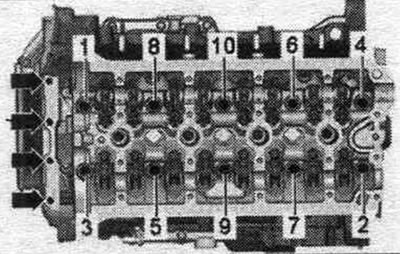
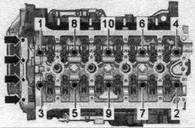
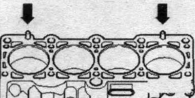
Remove the arrow bolts. Loosen the cylinder head bolts in sequence. "1...10".
Cylinder head bolt tightening sequence
Tighten the cylinder head bolts in sequence. "1...10" as follows.
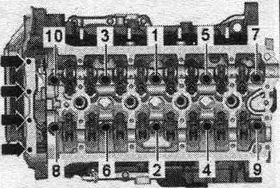
1. Pre-tighten to 40 Nm; 2/3. Tighten 90° with a regular wrench; 4. Pre-tighten the arrow bolts to a torque of 8 Nm; 5. Tighten the arrow bolts with a hard wrench by 90°.
Removal and installation the cylinder head
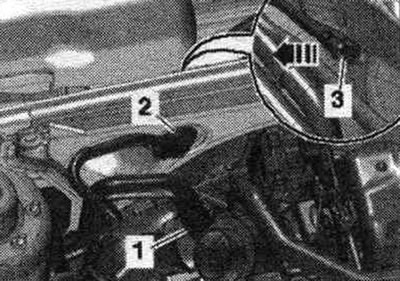
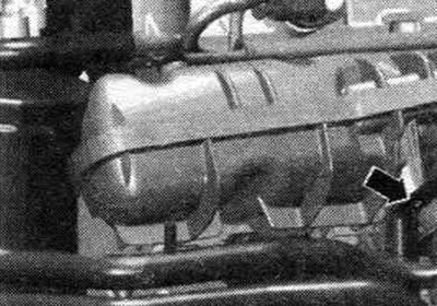
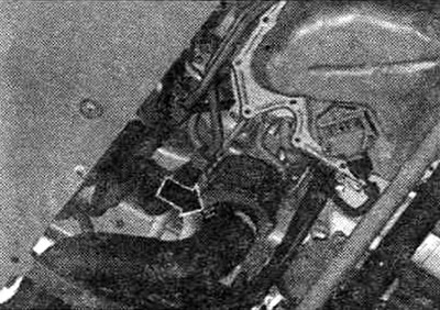
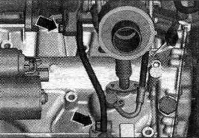
Camshafts without bolt free play do not have recesses in the camshafts. When reassembling, install all binders in the places where they were originally installed. Close the open channels of the intake circuit and system tightly. OG with corresponding plugs. For example, from the "VAS 6122" engine plug kit. Remove the camshafts. Risk of damage to valves and piston crowns. Once the camshafts are removed, the crankshaft can no longer be rotated. Remove the downpipe/front muffler. Remove the covers of the water drainage box "1, 2, 3".
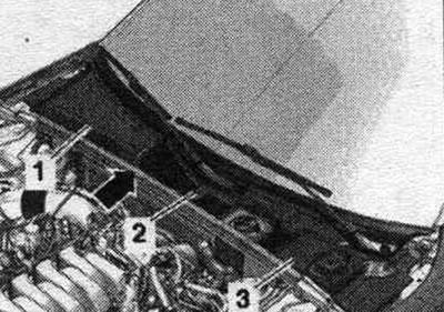
Remove the vacuum hose "2" from the end wall of the water deflector box; to do this, disconnect the vacuum hose "3" on the rear side "arrow". Remove the rear coolant hoses to the cylinder head.
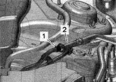
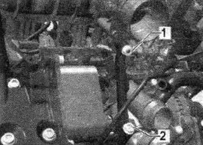
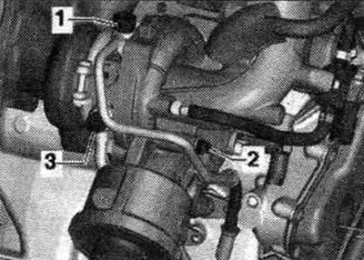
Disconnect the fuel. highways "1 and 2".
Loosen the "arrow" hose clamps and remove the air duct hose.
Disconnect the following connectors.
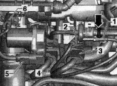
2. Unfasten from knock sensor 1 "G61" and release; 3. From the intake manifold flap valve "N316", fuel pressure sensor "G247" and Hall sensor "G40"; 4. From the injectors; 5. From the throttle body "J338"; 6. From the intake air temperature sensor "G42".
Disconnect connector "2" and release the wire.
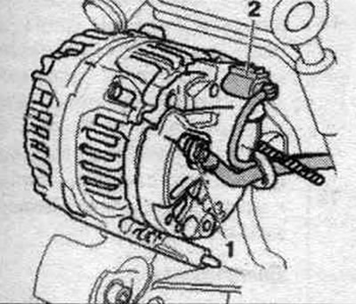
Unscrew the coolant line bracket "arrow". For better visualization, the installation position is shown with the engine removed.
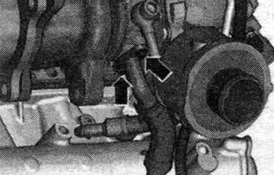
Remove the inlet pipe branch pipe by unscrewing the fastening nut "1" and bolt "2".
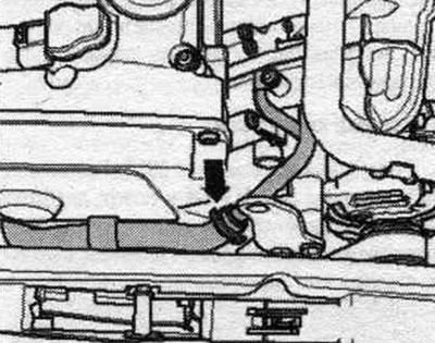
Disconnect the coolant hose "arrow".
Unscrew bolts "1 and 2" and put the oil supply line aside. Unscrew bolt "3" and move the coolant line to the side.
Disconnect the hose clamp "arrow", remove the air duct hose and set it aside.
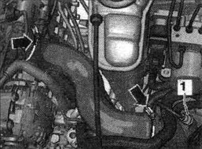
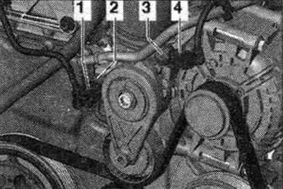
Disconnect connectors "1 and 4" from the oil pressure sensor "F22" and the low pressure oil pressure sensor "F378".
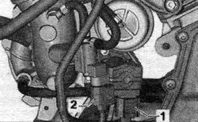
Disconnect connectors "1 and 2" and release the wire.
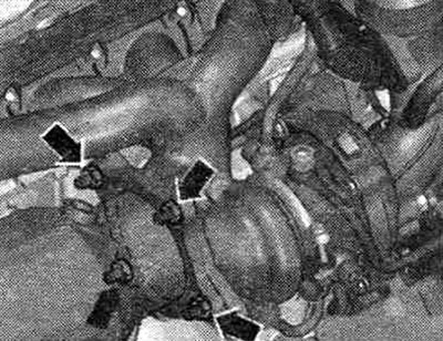
Unscrew the arrow bolts and remove the turbocharger support.
Unscrew the bolts "arrow" of the oil drain pipe.
Unscrew the arrow nuts and move the catalytic converter back. Unscrew the spark plugs using the spark plug wrench "3122 B".
Unscrew the "arrow" bolts. Unscrew the cylinder head bolts in sequence. "1...10". Check that all wires and cables are free! Pay attention to the tensioner bar and chain guide bar when lifting the cylinder head. Remove the cylinder head. Place the cylinder head on a soft pad (foam).
Installation
Caution! Risk of damage to the sealing surface. Carefully remove any remaining sealant from the cylinder head and cylinder block. Avoid creating long scratches or burrs. Risk of damage to the cylinder block. There should be no oil or coolant in the blind holes of the cylinder head bolts. Risk of a leaky cylinder head gasket. Carefully remove any remaining residue after sanding and grinding. The new cylinder head seal should be removed from the packaging immediately before installation. To prevent damage to the silicone layer and the grooves of the cylinder head gasket, handle the gasket with particular care. Risk of damage to open valves. When installing a replacement cylinder head, remove the plastic base to protect the exposed valves only when it comes into direct contact with the cylinder head. There is a risk of damage to the valves and piston crowns after working on the valve train. To ensure that no valves are touching the cylinder head during operation, carefully rotate the engine at least 2 revolutions. Replace any bolts that were overtightened. Replace all seals, gaskets and self-locking nuts. Consider different sealants for cylinder head sealing surfaces and bolts. Before installing a replacement cylinder head, lubricate the mating surfaces of the hydraulic lifters, rocker arms, and camshaft running surfaces with oil before installing the camshaft bearing housing. Hose fittings and air duct tubes and hoses syst. must be cleaned of oils and grease before installation. Secure all hose connections with hose clamps of the appropriate series.
Install the cylinder head gasket. Take into account the centering pins in the cylinder block "arrows". Take into account the installation. position of the cylinder head gasket, marking: the part number must be clearly visible from the intake side.
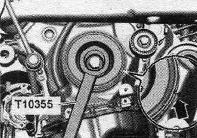
Make sure that the timing chain does not damage other components when turning the crankshaft. If the crankshaft has been turned, bring the piston of the first cyl. at TDC and again slightly turn the crankshaft back. Install the cylinder head. Insert the cylinder head mounting bolts and tighten them by hand. Retightening the cylinder head mounting bolts after repair work is not necessary. Turn the vibration damper with counter-support "T10355" to the "TDC" position "arrow". The notch on the vibration damper must be opposite the arrow mark on the lower timing chain cover.
Installation in reverse order. Install the camshafts. Install the upper drive chain cover. Change the oil. Replace the coolant. Install a catalytic converter. Install the downpipe/front muffler.
Compression check
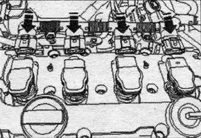
Oil temperature min. 30°C. Battery voltage at least 12.7 V. Remove the "arrow" motor cover. Unscrew the coil connector bolts. Unlock the "arrow" plugs and disconnect all the plugs from the coils at the same time.
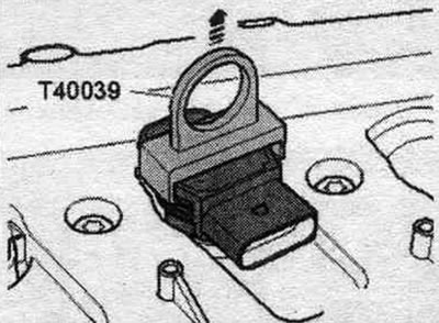
Remove the coils using the T40039 puller. Remove the spark plugs using the 3122 B spark plug wrench. Check the compression pressure using a compression gauge and adapter "VAG 1763/6".
Turn the starter until the compression gauge readings stop increasing.
Install spark plugs. Install coils with output stages. When plug connections are disconnected, errors are written into the memory. After measuring, interrogate and, if necessary, erase the fault memory. Interrogate the fault memory of the engine control unit using the VAS 5051 tester, "Guided Fault Finding" function.
Compression check
| New, excess bar; pressure | Wear tolerance limit, bar overpressure | Difference between cylinders, bar excess pressure |
| 11,0...14,0 | 7,0 | max 3.0 |
This article was previously published on the resource AudiManual.ru