
Table of contents: Drive chain covers ↓ Upper timing chain cover - sequence,… ↓ Lower chain drive cover - tightening… ↓ Removal and installation the upper… ↓ Removal and installation the lower… ↓
Drive chain covers
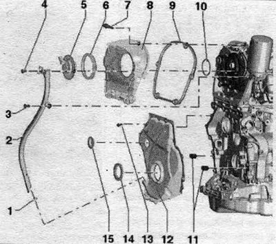
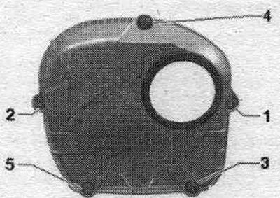
1. Sealing ring: replace, lubricate before installation. 2. Oil dipstick guide tube. 3/4. Bolt: 9 Nm. 5. Valve 1 for adjusting the timing phases "N205". 6. Sealing cuff: lubricate before installation; if damaged, replace.. 7. Bolt. 8. Upper drive chain cover. 9. Gasket: replace if damaged. 10. Sealing ring: replace: lubricate before installation. 11. Dowel pins: centering the cover. 12. Lower timing chain cover. 13. Bolt: replace. 14. Vibration damper shaft gasket: replace. 15. Plug: replace.
Upper timing chain cover - sequence, tightening
Tighten bolts "1 to 5" as shown in the figure sequ..
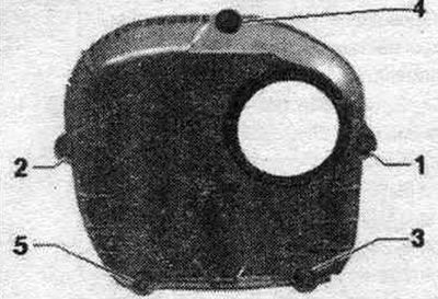
1. Tighten the bolts to 9 Nm.
Lower chain drive cover - tightening sequence
Tighten bolts "1 to 15" in 2 stages as shown in the figure sequ..
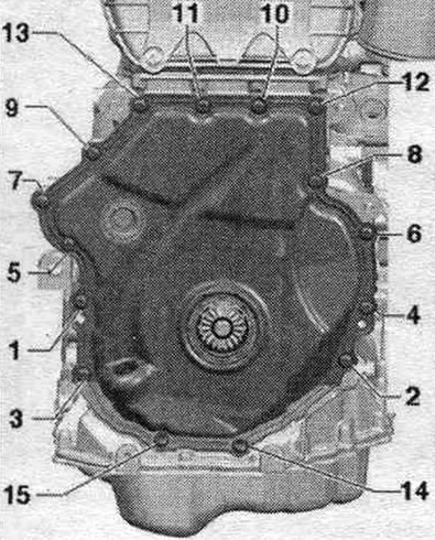
1. Tighten the bolts to 8 Nm; 2. Tighten the bolts by 45°.
Removal and installation the upper timing chain cover
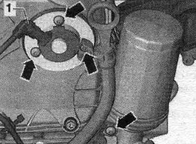
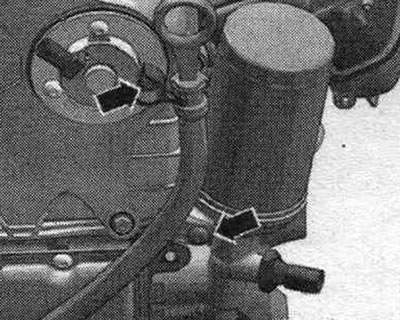
Disconnect the plug of the valve 1 of the variable valve timing system "N205" "1". Unscrew the bolts "arrows" and remove the valve 1 of the variable valve timing system "N205".
Remove bolts "1 through 5" and remove the upper timing chain cover.
Installation
Installation in reverse order. Replace the seal. ring. Lubricate the sealing cuff and gasket. ring with oil. Install the upper cover of the drive chain, sequence, tightening. Install valve 1 of the timing phase control system "N205".
Removal and installation the lower timing chain cover
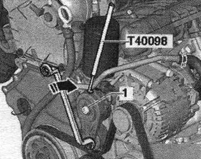
Remove the front sound insulation. Remove the front bumper trim and bumper. Bring to service position. To loosen the poly V-belt, turn the tensioner in the direction of the arrow. Secure the tensioner with the T40098 clamp. Loosen bolt 1 and remove the poly V-belt tensioner from the accessory holder. units. Remove the poly V-belt.
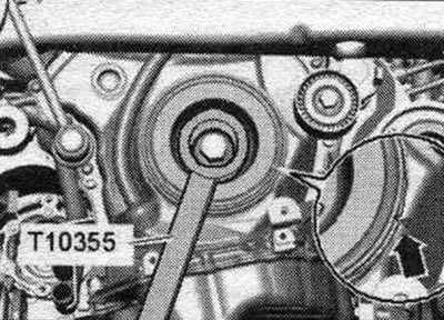
Turn the vibration damper with counter-support "T10355" to the "TDC" position "arrow". The notch on the vibration damper must be opposite the arrow mark on the lower timing chain cover. Unscrew the damper bolt using the T10355 counter support. Remove the vibration damper. To avoid damaging the gear engagement, screw in the damper bolt only with the T10368 mandrel.
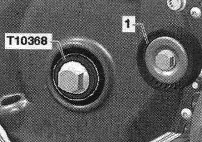
Reinstall the damper bolt and drift "T10368." To avoid adjusting the timing, do not rotate the crankshaft past the "TDC" position with the damper bolt removed. Remove guide roller "1.".
Unscrew the arrow bolts and remove the oil level dipstick guide tube from the drive chain cover.
Unscrew bolts "1...15".
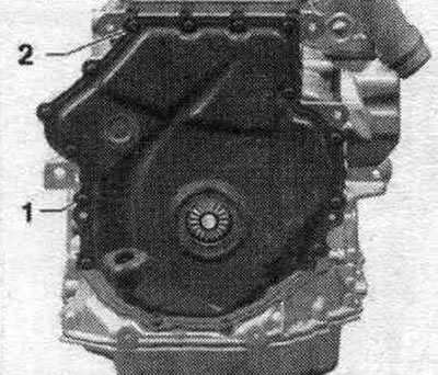
Press down on the bottom chain cover starting from the "1 and 2" eyelets.
To avoid deformation, do not grip between the bolt placement points.
Installation
Take into account the expiration date of the silicone sealant. The lid must be installed within 5 minutes after applying the silicone sealant. Replace bolts that were tightened with additional tightening. Replace all seals, gaskets and self-locking nuts. Spray the seating surface with sealant remover and allow time for it to take effect. Remove any remaining sealant from the cylinder block using a flat scraper. To prevent contamination from entering, tape the shaft sealing cuff on both sides with electrical tape. Remove any remaining sealant from the lid, for example,
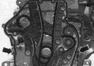
using a drill with a rotating plastic brush attachment, clean the sealing surfaces of oil and grease. Install the cover with the old bolts and tighten the bolts to 8 Nm. Using a feeler gauge, check the gap between the cover and the crankcase; it should be no more than 0.2 mm. If the gap exceeds 0.2 mm, the cover must be replaced. Between the lid and the top of the oil. do not measure the gap on the pallet, but conduct a visual inspection to ensure the seating surface is even. Check that both dowel pins are present to center the "arrow" cover.
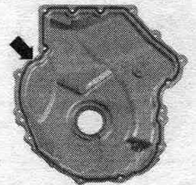
Cut off the tip of the tube along the front mark (hole diameter is about 3 mm). Apply silicone sealant to the clean surface of the lid seal as shown in the figure. Sealant bead thickness: 2-3 mm. The sealant bead should not be thicker than the specified width, otherwise excess sealant may enter the oil pan and clog the mesh filter in the oil intake pipe.
Install the cover immediately and tighten the bolts. After installing the cap, allow the sealant to dry for about 30 minutes. Only then can you add oil. Install the tensioner for the poly V-belt. Install the poly V-belt. Return to service position. Install the front bumper cover and bumper. Install the front noise insulation screen. Check the oil level.