



Table of contents: Removal the engine ↓ Engine installation ↓ Unit supports ↓ Removal and installation the engine… ↓
Removal the engine
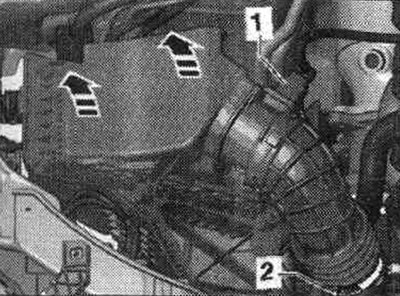
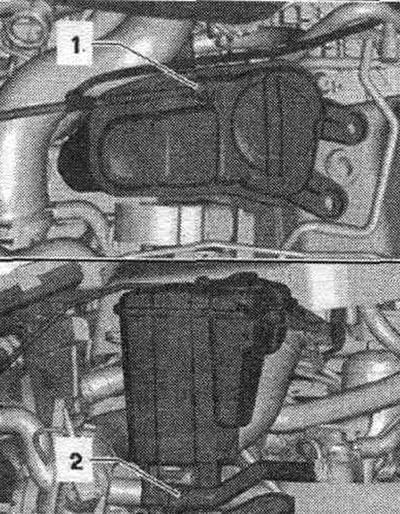
Note: Remove the engine without the gearbox in an upward direction. During installation, all cable ties should be placed in their original locations. To be able to rotate the driveshaft on a four-wheel drive vehicle for removal, the power must be turned off before disconnecting the battery. mechanical parking brake. Disconnect the battery. Remove the front wheels: right and left. Remove the front right and left fender liner. Remove sound insulation. Bring to service position. Remove the downpipe/front muffler. Disconnect connector "1" of air flow meter "G70". Release air intake pipe "2". Remove air flow meter housing. filter up "arrows".
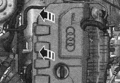
Remove the "arrow" engine cover.
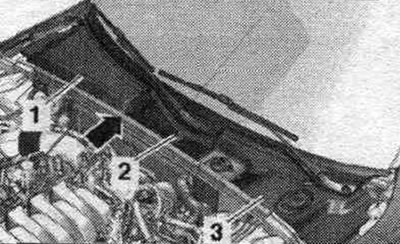
Remove the "arrow" gasket. Disconnect and remove gaskets "1, 2, 3" from the water drainage box cover.
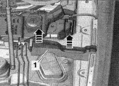
Remove the left and right elements "1" from the foam upwards in the direction of the "arrows".
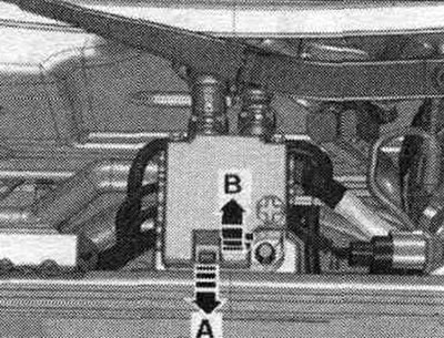
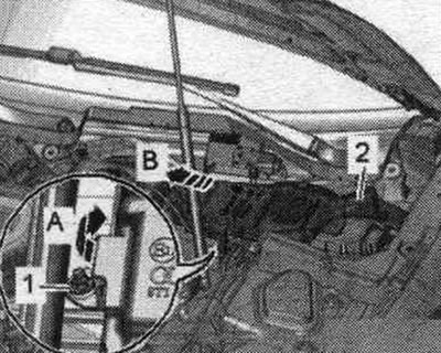
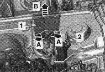
Unlock the lock "arrow A" and open the cover "arrow B".
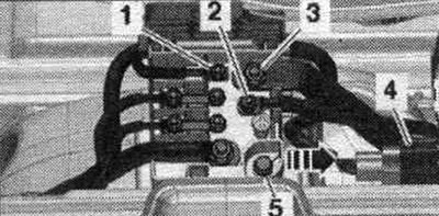
Loosen the nuts "1...3" of the wires. Remove the plug connection "4" from the holder and disconnect it. Unscrew "5" and remove the wire distributor from the "arrow" stretcher.
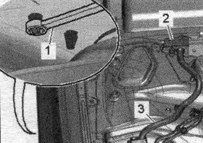
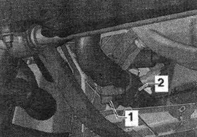
Unlock the retainers on the wheel arch side using a 5.5 open-end wrench "pos. 1" and remove the pass-through insulator "2" upwards.
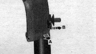
Open the cable channel by unlocking the lock "arrow B", pull the cable channel forward "arrow A" and release the wires.
Unscrew the nut "1" and tilt the filler neck of the washer fluid reservoir slightly forward "arrow A". Remove the filler neck "2" with the filler tube from the washer fluid reservoir, passing it through the body opening "arrow B".
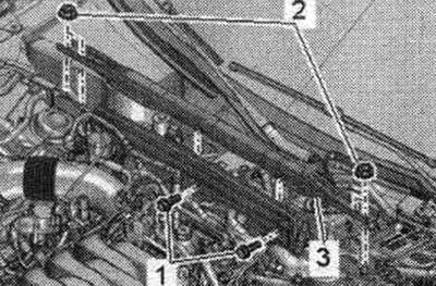
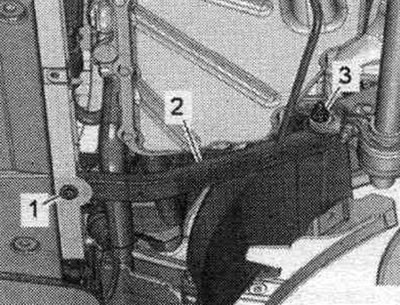
Unscrew bolts "1" and nuts "2" and remove stretcher "3".
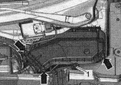
Unscrew the arrow bolts and remove the cover of the motorcycle switching unit. compartment. Unscrew nut "1" and release the wire.
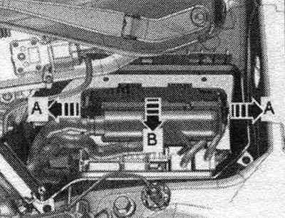
Unlock the "arrow A" fasteners and remove the "arrow B" engine control unit.
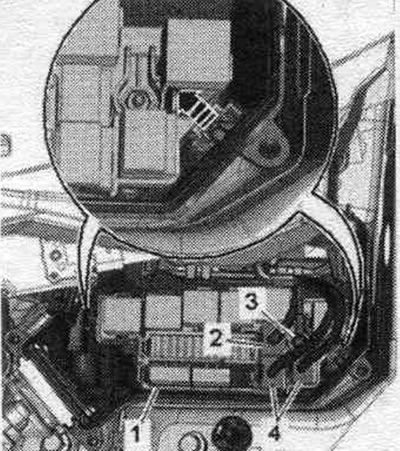
Disconnect the plug connectors "4" and unscrew the nut "3" securing the wire. Disconnect (if available) plug connector "2". Unlock the "arrow" latches and remove the relay and fuse holders "1".
Unlock the clamps "arrow A" and remove the cable guide "1" in the upward direction "arrow B". Disconnect the engine wiring harness at the junction box in the engine. compartment and release it. Place the wiring harness on the engine and secure the engine control unit from falling out.
Open the expansion lid. tank. Install a tray for service cranes under the engine. Screw drain cock "1" onto the fitting and drain the coolant, then remove fitting "2" from the radiator.
Unscrew nuts "3" on the left and right and remove longitudinal rods "2".
Disconnect the hose clamp "arrow", remove the air duct hose and set it aside.
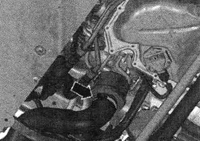
Unscrew the "arrow" nut on the right side member and release the ground cables. Unscrew nut "2" of the bracket with electrical wiring on the right side of the car.
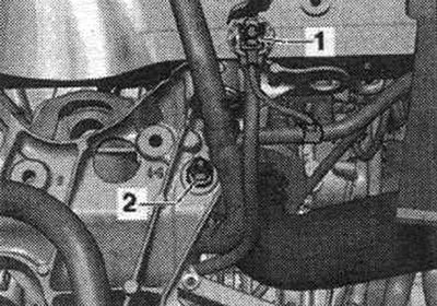
Disconnect the plug connection "1" of the radiator fan by moving the lock back "arrow" and pressing the stopper down. Place the wiring harness on the engine and secure it from falling.
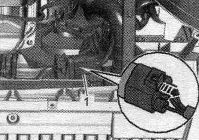
Remove the vacuum pipe "2" from the end wall of the water drainage box; to do this, disconnect the vacuum hose "3" on the rear side of the "arrow".
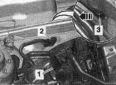
Unscrew nut "5", remove coolant hoses "1...4" and remove the end wall of the water drainage box.
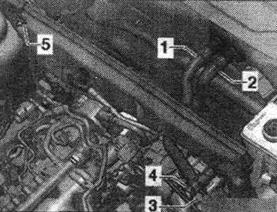
Unscrew bolts "2...6".
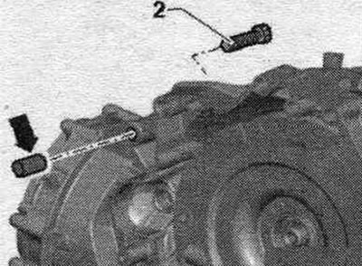
Bolt "2" secures the starter to the gearbox and has an additional. the "arrow" spacer sleeve. When removing and installing the engine, remember to use the "arrow" spacer sleeve. The spacer sleeve must be inserted between the starter and the transmission.
Remove coolant hose "2" and permanent exhaust "1".
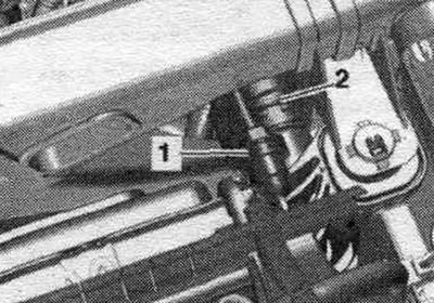
Remove the permanent exhaust "1" and coolant hose "2" from the coolant expansion tank.
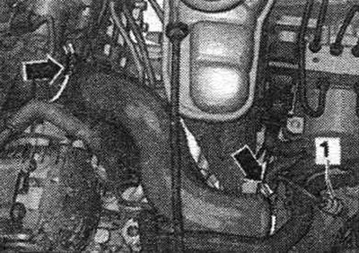
Loosen the "arrow" hose clamps and remove the air duct hose. Disconnect and release the plug connector of the boost pressure sensor "G31" "1". Remove the catalytic converter.
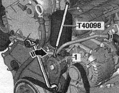
To reinstall the poly V-belt, mark the direction of rotation with chalk or a felt-tip pen before removing it. To loosen the poly V-belt, turn the tensioner in the direction of the arrow. Secure the tensioner with the T40098 clamp. Remove the poly V-belt.
Disconnect plug connection "1" of the electromagnetic clutch on the compressor. Unscrew the compressor "arrow" bolts.
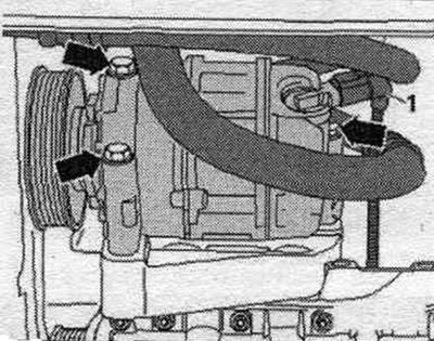
Tie the compressor with the refrigerant hoses connected to the side member from above. The hydraulic lines of the general purpose pump remain connected. Remove bolts "1" through the belt pulley at the front, and bolt "2" from the rear. The illustration shows the general purpose water pump without a belt pulley and without hydraulic lines.
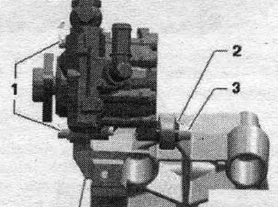
Place the general purpose water supply pump with the connected hydraulics. lines on the spar. Disconnect the supply "1" and return "2" fuel lines.
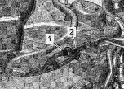
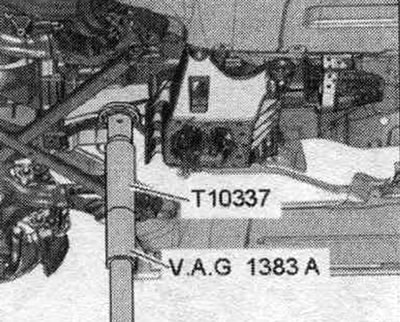
Support the gearbox using a tilter and a mounted gearbox support.
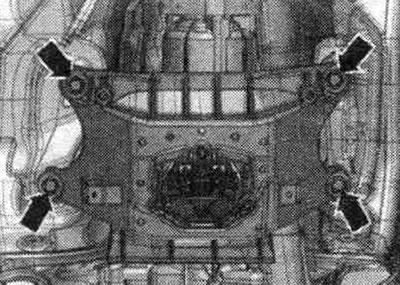
Loosen the tunnel cross member arrow bolts.
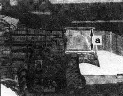
Lower the KP using the tilting device to dimension "a". Dimension "a" = max. 180 mm.
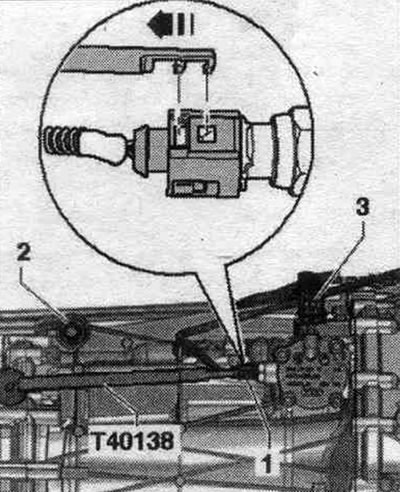
Disconnect and release the plug connector "1" of the reversing light switch "F4" using the puller "T40138".
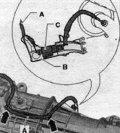
Unlock the electrical wire "A" from the gearbox and disconnect the electrical connector "C".
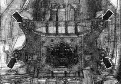
Raise the gearbox with a tilting device and screw in the tunnel crossmember arrow bolts.
Remove cover "1" from the bottom of the "arrow" gearbox.
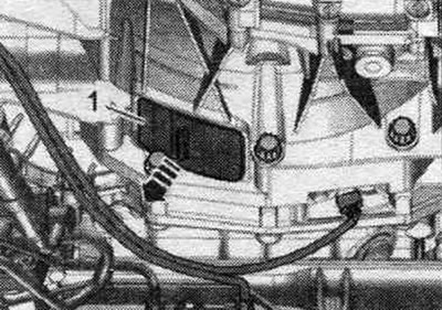
Remove 3 bolts "arrow" of the driven disk. To do this, turn the crankshaft 120° in the direction of engine rotation.
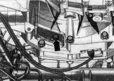
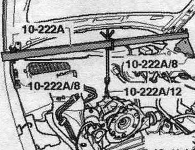
Unscrew bolt "1" of the starter from the engine side. Remove the starter from the gearbox and leave it in the mounting position. Loosen the remaining bolts "7...10" securing the engine to the gearbox. Install the "10-222A" crossmember with the "10-222A/8" adapter onto the shock absorber cups on the left and right, as shown in the figure. Connect the gearbox and lead screw with a "10-222 A/12" weight clamp. Shown with the engine removed for better clarity. Slightly pre-tension the spindles of the 10-222 A crosshead!
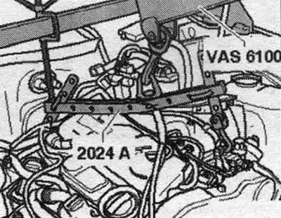
Hang the "2024 A" lifting device on the engine and the "VAS 6100" service crane as shown in the figure. The hooks and locking pins of the hanging device must be secured with pins.
Unscrew bolts "1" of the right and left engine mounts. "Arrow" should not be taken into account.
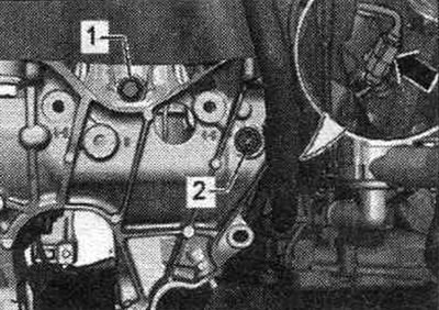
Raise the engine enough to clear the engine mounts. Tighten the lead screw of the 10-222 A crosshead. Risk of damage to hose and wire connections, as well as the motor. compartment. Make sure that all hose and wire connections between the engine, transmission, subframe, and body are disconnected. When removing the engine from the motorcycle. be careful when entering the compartment. Disconnect the engine from the gearbox and remove it upwards from the engine. compartment.
Engine installation
Tightening torques (Nm)
| Bolts and nuts | M6 | 9 |
| M8 | 20 | |
| M10 | 40 | |
| M12 | 65 |
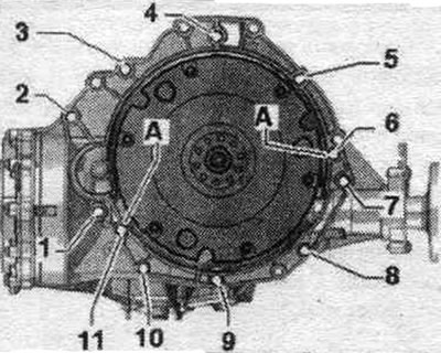
Fastening the engine to the manual transmission
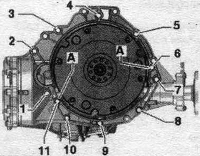
| Pos. | Bolt | Nm |
| 1(3) | M10 x 50 (1) | 65 |
| 2(3), 7 | M12 x 100 (2) | 30 + 90° |
| 3(4), 6 | M12 x 75 (2) | 30 + 90° |
| 4.5 (4) | M12 x 120 (2) | 30 + 90° |
| 8...10 | M10 x 75 (2) | 15 + 90° |
| 11 | M12 x 50 (2) | 30 + 90° |
| A | Alignment bushings | |
(1) Steel bolt - do not replace.
(2) Replace the bolts.
(3) Additionally secures the starter.
(4) Additionally secures the cable mount.
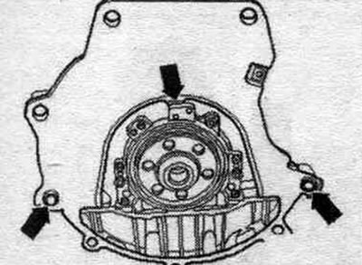
Note: Replace bolts that have been over-tightened. Replace self-locking nuts, lip seals, gaskets and seals. rings. Hoses and hose fittings syst. air boosters must be cleaned of oils and grease before installation. Secure all hose connections with hose clamps of the appropriate series. During installation, all cable ties should be placed in their original locations. Check the presence of bushings in the cylinder block for centering the engine and gearbox; insert bushings if necessary. Be sure to clean the threaded holes for securing the power unit in the cylinder block before assembling the transmission with a tap. Before securing the engine to the transmission, check that the intermediate shield is suspended on the flange and that the "arrows" are seated on the mounting bushings.
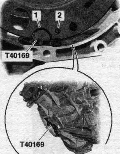
Insert the mounting device "T40169" from below into the gearbox housing and install the clutch module as shown in the figure. The T40169 auxiliary tool should fit into the semicircular recess "1" and into the inspection hole "2." To locate the inspection hole, rotate the clutch module.
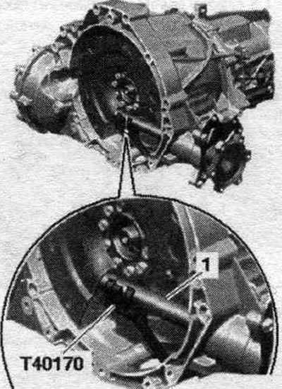
Insert the "T40170" bracket from below into the gearbox housing and secure the bracket to the axle shaft with flange "1".
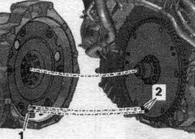
The following action is necessary if the driven disk is installed with the locking pin "2". Align the additional. driven disk in relation to the clutch module so that the locking pins "2" (if available) on the driven disk entered the large holes "1" on the clutch module. If the locking pins of the driven disc "2" are not located in the holes of the clutch module "1", this can lead to significant problems with the operation of the clutch.
Bolt "2" secures the starter to the gearbox and has an additional. the "arrow" spacer sleeve. When removing and installing the engine, remember to use the "arrow" spacer sleeve. The spacer sleeve must be inserted between the starter and the transmission.
Install the gearbox onto the engine and tighten bolts "7...11" connecting the engine and gearbox. Release the lead screw of the "10-222 A" crossmember. Lower the service crane and place the engine and gearbox on the engine mounts. Screw in bolts "1" of the right and left engine mounts. Remove the crane and suspension device. Screw in and tighten bolts "1...6" for fastening the engine to the gearbox. "Pos. A" should not be taken into account. Remove bracket "T40170" and installation tool "T40169." This step is necessary to ensure the clutch module fits evenly on the driven disc and does not warp. Lightly press clutch module "2" using mounting lever "1" onto clutch driven disc "3" "in the direction of the arrow".
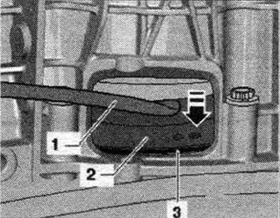
Tightening sequence - clutch module to driven disc
Tighten the first "arrow" bolt by hand.
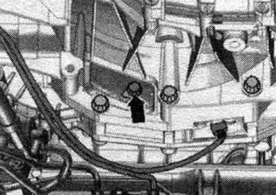
Turn the crankshaft 120° in the direction of engine rotation and tighten the 2nd bolt by hand. Turn the crankshaft another 120° in the direction of engine rotation. Now tighten bolt 3 to the specified tightening torque. Now tighten the remaining bolts to the specified torque. Installation in reverse order. Install the starter. Install the catalytic converter. Install the downpipe/front muffler. Install the exhaust system. without stress. Install the compressor. Install the poly V-belt. Electrical connectors and wiring. Install the engine control unit. Install the wires, the 2-way splitter 30 "TV22" and the cover of the motor junction box. compartment. Install the stretcher. Install the washer reservoir filler neck. Follow the instructions after connecting the battery terminals. Install the air conditioner housing. filter. Return to the service position. Check the oil level. Fill with coolant. Install noise insulation screens and fender liners.
Unit supports
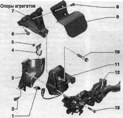
1. Not installed. 2. Bolt: 20 Nm. 3. Engine mount gearbox retainer; if the engine mount is defective, replace the mounting plate; check the mounting plate on the opposite side and replace it if necessary. 4. Holder: for hydraulic line. 5. Nut: 9 Nm. 6. Bolt: 40 Nm. 7. Engine support. 8. Bolt: 10 Nm. 9. Thermal insulation. 10. Bolt: replace; 90 Nm + 90° rotation. 11. Engine mount: with solenoid valve of the left electrohydraulic engine mount "N144" (only on the left); be replaced only in pairs. 12. Subframe. 13. Bolt: 55 Nm.
Removal and installation the engine mount
Replace engine mounts only in pairs, left and right. The corresponding mounting shields are also replaced along with them. Remove the engine cover "arrows". Remove the tensioner. Install the "10-222 A" crossmember on the shock absorber strut cups on the left and right, as shown in the figure.
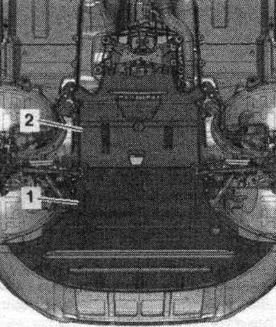
Attach the lead screw "10-222 A/11" to the rear engine suspension eye. Tighten the engine slightly with the lead screw. Remove the left front wheel. Remove the front noise insulation "1". Remove the front left fender liner.
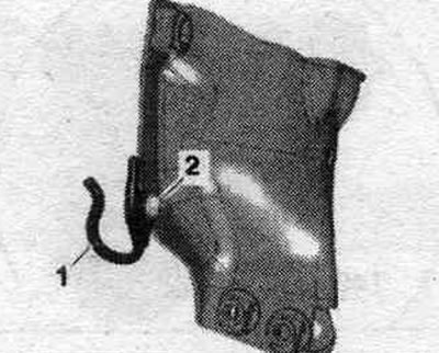
Unscrew nut "2" and release bracket "1".
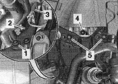
Release and disconnect the plug connector "3" of the solenoid valve of the left electrohydraulic engine mount "N144". Unscrew the bolts "1, 4, 5" of the engine mount. Set aside the engine mount mounting plate "2". Remove the engine mount.
Installation
Installation in reverse order. Replace bolts that were tightened with additional tightening. Install the fender liner and sound insulation. Install the front wheel. Install a stretcher.
[This article was copied from an online resource: AUDImanual.ru]