
Table of contents: Removal ↓ Installation ↓
Removal
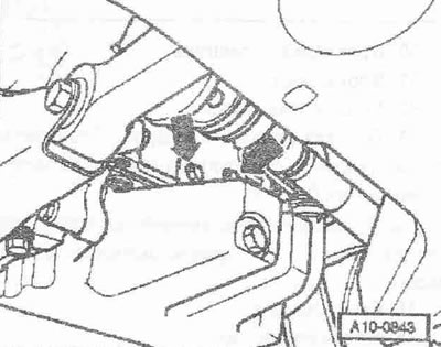
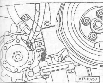
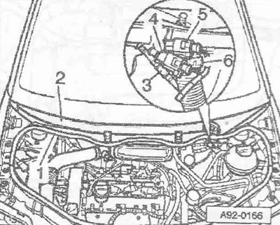
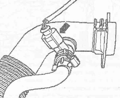
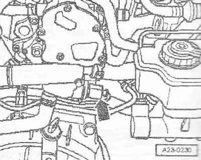
Observe safety precautions when disconnecting the battery. The battery is located in a hidden niche of the trunk. Turn off the ignition and remove the key from the ignition switch. Disconnect the ground wire "arrow" from the battery. Remove the hood. Drain the coolant. Remove the catalytic converter. Remove the poly V-belt. Unscrew the heat shield of the left drive shaft "arrow".
Vehicles with letter designation AMF
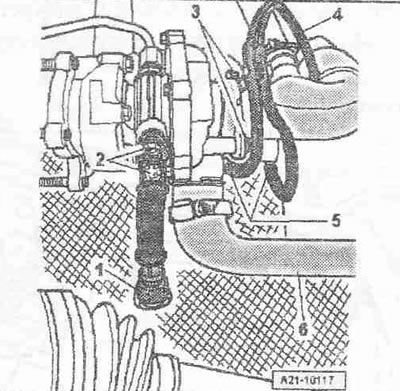
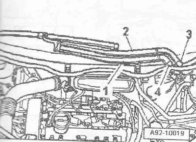
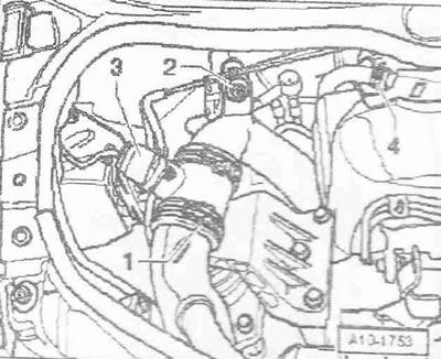
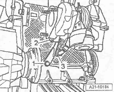
Disconnect the air duct hose "6" from the turbocharger. Disconnect the hoses "5" of the boost pressure control system to the turbocharger and the boost pressure control pneumatic power element. Disconnect the ventilation hose "4". Unscrew the bolts "3" and remove the air guide pipe from the turbocharger.
Instructions. The air guide pipe remains in the installation position and is removed later in the upward direction. Pos. "1" and "2" are not to be taken into account.
Vehicles with the letter designation ATL, VNS
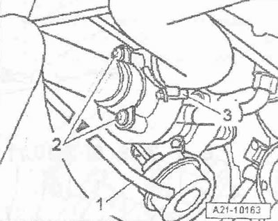
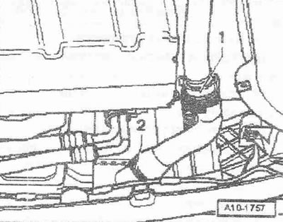
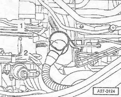
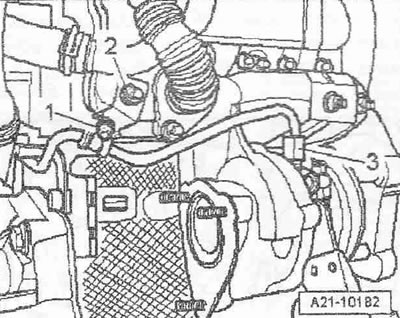
Remove the vacuum hose "1" from the boost pressure control power vacuum pneumatic element and set it aside. Unscrew the bolts "2" and remove the air guide pipe from the turbocharger.
Instructions: The air guide pipe remains in the installation position and is removed later in an upward direction.
Disconnect the air duct hose "3" from the turbocharger.
All cars
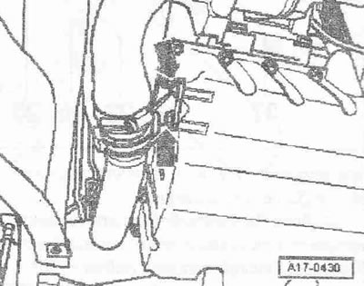
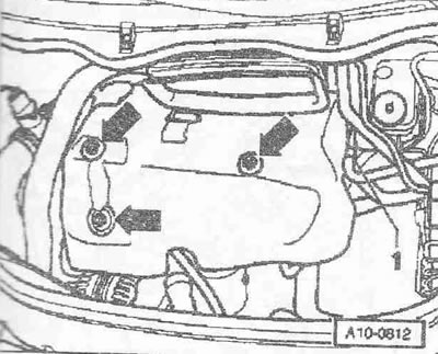
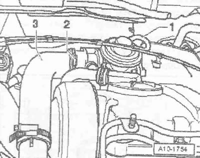
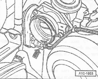
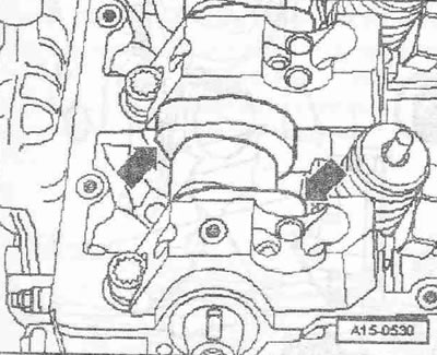
unscrew the air guide pipe bracket from the oil pan "arrows". Remove the right air duct hose "2" from the intercooler. Ignore pos. "1".
Disconnect the plug connector of the oil level and temperature sensor "G266". Loosen the electrical wiring. Depending on the version, the oil level and temperature sensor "G266" may be located at the front on the oil pan.
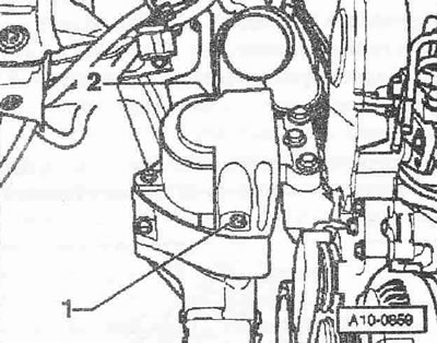
If available, loosen bracket "1". Remove the engine cover "arrows". Remove the sound insulation underneath.
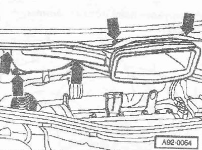
Lift the caps "3 and 4" of both parts of the windshield wiper arm with a screwdriver. Loosen the nuts of both parts of the windshield wiper arm with a few turns. Loosen the arms "1 and 2" of the windshield wiper on the axles one by one with light rocking movements. Completely unscrew the nuts and remove both parts of the windshield wiper arm. If it is not possible to remove the arm in this way, then in this case it is necessary to use a standard puller.
Disconnect the washer fluid supply pipe "3". If present, disconnect the plug connectors "4 and 5" of the heated windshield washer sprayers. Loosen the hose clamp "6" using hose clamps "V.A.G 1921" and remove the drain hose from the deflector grille. Remove the rubber seal "1" of the deflector grille. Remove the deflector grille "2".
Loosen the nuts and bolts of the "arrow". Pull the fresh air supply duct forward and remove it, turning it to the right side of the car.
Vehicles with letter designation AMF
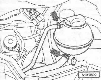
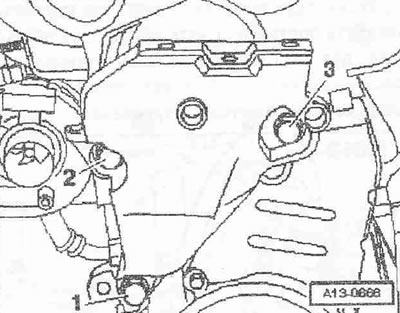
Disconnect the air duct hose "2" from the mechanical EGR valve. Disconnect the vacuum hose "3" of the mechanical EGR valve. Disconnect the vacuum hose "4" of the intake manifold flap power vacuum pneumatic element.
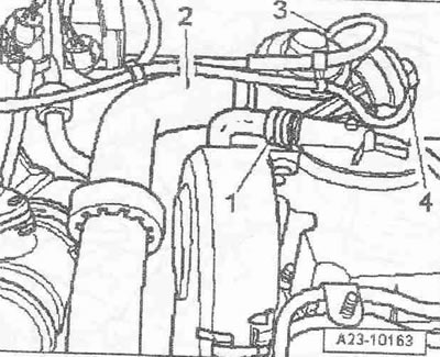
Remove the air duct hose "2" from the intercooler. "Pos. 1" is not taken into account.
Vehicles with the letter designation ATL
Remove the air duct hose "3" from the intake manifold flap motor "V157" by slightly loosening the clamp "2". Disconnect the vacuum hose "1" of the mechanical EGR valve.
Remove the air duct hose "2" from the intercooler. Disconnect the plug connector of the boost pressure sensor "G31" pos. "1".
All cars
Warning! Risk of burns from contact with fuel lines or fuel heated to 100°C. Wait until the fuel has cooled before opening the fuel line connections.
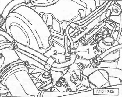
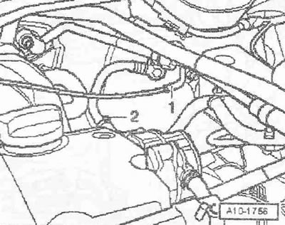
Mark and disconnect the fuel pre-supply line "2" and the fuel return line "1". Unfasten the fuel lines.
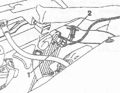
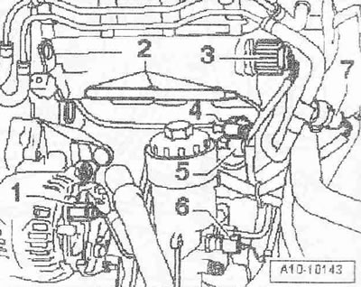
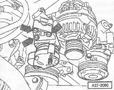
Disconnect the air duct hose "1" from the air flow meter "G70". Disconnect the plug connector "3" of the air flow meter "G70". Unscrew the nut "2". Remove the crankcase ventilation hose "4" from the cylinder head cover. Pull out the air guide pipe together with the air flow meter "G70".
If present, disconnect the plug connector "arrow" of the crankcase ventilation heating element "N79". Remove the air guide pipe.
Vehicles with the letter designation ATL
Disconnect the "arrow" connector of the intake manifold flap motor "V157". Loosen the wiring.
All cars
Remove the drain hose "2". Remove the water intake tank "1".
Remove the left upper coolant supply hose "pos. 1 and 2".
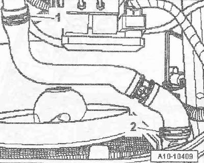
Mark the coolant pre-supply hose "1" and coolant return hose "2" to the heater heat exchanger and remove the coolant hoses on the front shield.
Vehicles with the letter designation ATL, VNS
Disconnect vacuum hose "1".
All cars
Remove vacuum hose "2" from the tandem pump to the brake booster.
Loosen the vacuum hoses.
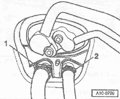
Disconnect the plug connectors "2" of the glow plugs. Pull out the release pin and unscrew the knurled nut "3" of the central connector of the pump-injector module. Disconnect the plug connector of the Hall sensor -040 "pos." 4-. Disconnect the plug connector "7" of the fuel temperature sensor "G81". Ignore pos. "1, 5, b".
Remove the oil pre-supply line "2" to the turbocharger from the oil filter bracket. Unscrew the bracket of the oil pre-supply line "3". Ignore pos. "1".
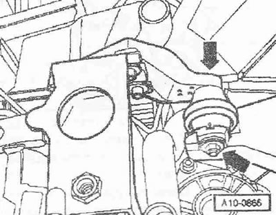
Disconnect the "arrow" connector of the coolant temperature gauge sensor "G62"
Unscrew the electrical wiring harness bracket from the coolant supply nipple "arrow". Unfasten the wiring harness.
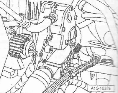
Remove the upper coolant supply hose from the expansion tank -upper arrow- and set it aside.
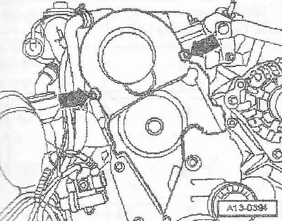
Unscrew the poly V-belt tensioner "arrows".
Remove the upper part of the belt guard "arrows".
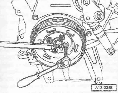
Unscrew the torsional vibration damper; to do this, hold the crankshaft by the central bolt with an open-end wrench.
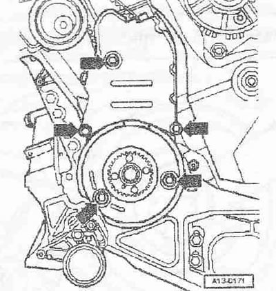
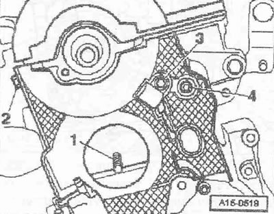
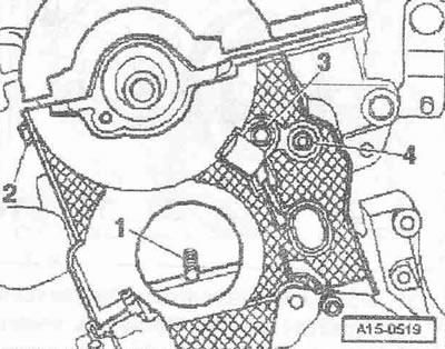
Unscrew the central and lower parts of the belt guard "arrows". Unscrew the lower bolt "1" of the engine support. Bolts "2 and 3" are unscrewed later.
Vehicles with the letter designation ATL, VNS
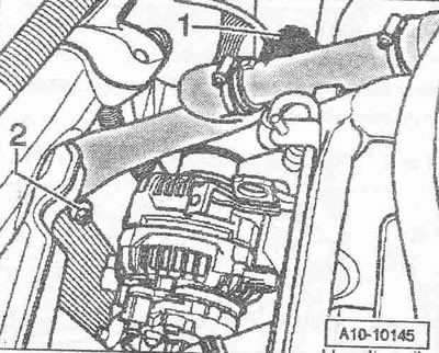
Unscrew bolts "1 and 2" and remove the turbocharger support.
All cars
Remove the oil return pipe "3" from the cylinder block.
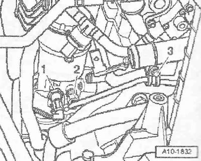
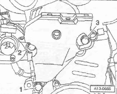
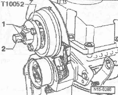
Loosen bolt "1" by about 3 turns. Unscrew nut "2". Unscrew oil return pipe "3" from turbocharger and put it aside.
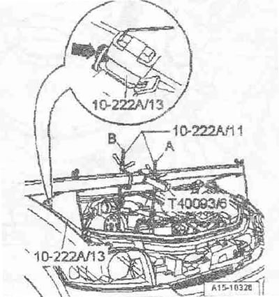
Install the crossmember "10.222 A" with adapters "10.222 A/13" and adapter "T40093/6" on the edges of the bolted joints of the wings.
Caution! Insert the adapter "10.222 A/13" into the hood catches "arrow".
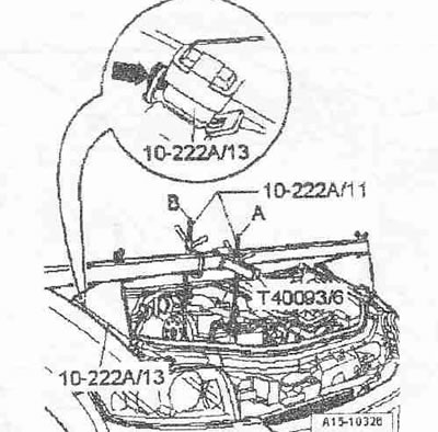
The clamp screw in the adapter "T40093/6" must be unscrewed. The adapter "T40093/6" is installed so that its bracket faces upward. Hook the hook of the lead screw carabiner -10.222 A/11 —pos. A- to the engine eye. Tighten the engine with the lead screw "A" without lifting it. The additional right lead screw "pos. B" remains free for now.
Car with engine mount cover
Remove the engine mount cover by unscrewing bolts "1 and 2".
Unscrew bolts "1 and 3" and remove the bracket with engine mount "2".
Cars without engine mount cover
Nut "3" can only be loosened to replace the engine mount.
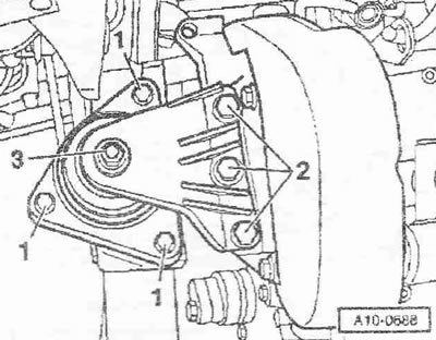
Unscrew bolts "1 and 2" and remove the bracket with the engine mount.
All cars
Remove the upper bolts "2 and 3" and remove the engine support.
Caution! The engine may only be turned by the crankshaft in the direction of its rotation (clockwise). To rotate the engine shaft, install the center bolt on the crankshaft.
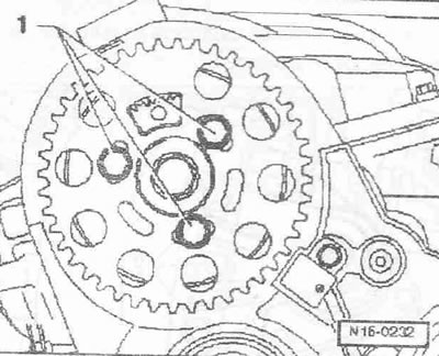
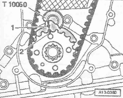
Set the crankshaft to the "TDC" mark. The gap between both teeth of the camshaft sprocket should be opposite the "37." mark on the rear part of the belt guard "arrows". Fix the camshaft bushing with the "3359" lock. Fix the crankshaft sprocket with the "T10050" crankshaft stopper.
Instructions: The crankshaft stopper can only be pushed onto the sprocket teeth from the outside.
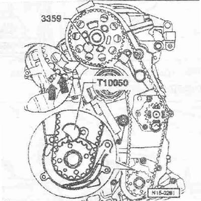
The markings on the sprocket and the crankshaft stopper "T10050" must be opposite each other. In this case, the journal of the crankshaft stopper "T10050" must enter the hole in the sealing flange. Remove the toothed belt: toothed belt drive with a hydraulically damped tension roller, toothed belt drive with a friction-damped tension roller. Unscrew bolts "1" and remove the camshaft sprocket from the bushing.
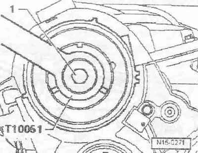
Loosen the bolt "1" of the bushing, holding the shaft with the key "T10051" from turning. Then unscrew the bolt by about 2 turns.
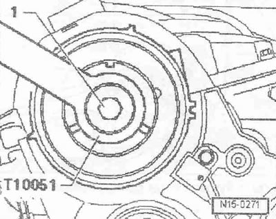
Loosen the bolt "1" of the bushing, holding the shaft with the key "T10051" from turning. Then unscrew the bolt by about 2 turns.
Remove the timing belt tension roller. Unscrew bolts "2...4". Unscrew the mounting pin "1" using 2 M8 nuts locked against each other.
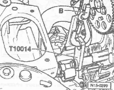
Screw the bracket "T10014" into the threaded hole above the cooling pump. Hook the hook of the free-running screw -10.222 A/11. pos. "B" onto the bracket "T10014".
Lift the engine with lead screw "B" until lead screw "A" is unloaded. Remove lead screw "A" and move it to the side.
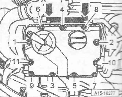
Loosen the cylinder head cover bolts according to the sequence "11...1". - arrow, take into account.
Remove the bracket together with the fuel lines. Remove the cylinder head cover.
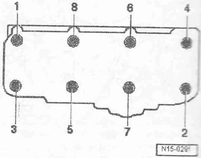
Loosen the cylinder head bolts according to the sequence "1...8". The second mechanic should carefully remove the cylinder head, lifting its top. Place the cylinder head with the combustion chamber up on a soft mat.
Installation
Instructions. Replace the cylinder head mounting bolts. Replace the self-locking nuts and bolts. Replace the bolts tightened to a certain angle, as well as the cuffs and seals. When repairing, carefully remove any remaining sealant from the cylinder head and cylinder block. Avoid the formation of long scratches or burrs. Carefully remove any remaining emery and sanding material. There should be no oil or coolant in the blind holes of the cylinder head mounting bolts. Remove the new cylinder head gasket from the packaging immediately before installation. Handle the gasket with extreme care. Damage to the silicone layer and corrugated joints will result in loss of tightness. Cylinder heads with cracks between the valve seats can be used without reducing their service life if the crack width does not exceed 0.5 mm. Modification of a diesel cylinder head is unacceptable. When installing a replaced cylinder head with the camshaft installed, the contact surfaces between the hydraulic tappets and the sliding surfaces of the cams must be lubricated with oil. The plastic linings included in the repair kit for protecting open valves may be removed immediately before installing the cylinder head. Use clamps of the appropriate series to secure all hose connections. After replacing the cylinder head or cylinder head gasket, it is necessary to replace the coolant and oil. After working on the valve mechanism, turn the engine manually at least 2 revolutions to ensure that no valve is in contact with the piston.
Check the position of the camshaft and crankshaft relative to the "TDC" mark: the camshaft cams of cylinder 1 should be symmetrically facing the top of the "arrow".
The crankshaft sprocket must be secured with the crankshaft stopper "T10050". The markings on the sprocket and the crankshaft stopper "arrow" must be opposite each other. In this case, the crankshaft stopper journal must enter the hole in the sealing flange.
Take into account the markings on the cylinder head gasket.
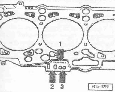
1. Part number
2. Control code (disregard)
3. Holes
Instructions. In case of replacement of the cylinder head gasket or cylinder head, install a new gasket with identical marking. In case of replacement of crank mechanism parts, it is necessary to re-determine the required thickness of the cylinder head gasket by measuring the piston protrusion at TDC.
Install the cylinder head gasket. Watch the centering bushings in the cylinder block. Take into account the installation position of the cylinder head gasket, the "oben/top" mark or the part number must point to the cylinder head. Install the cylinder head. In the cylinder head, check the installation of all cylinder head bolt washers. Insert new cylinder head mounting bolts and tighten them by hand.
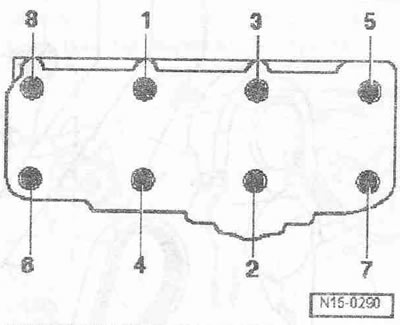
Tighten the cylinder head bolts in 4 stages in the specified sequence as follows:
- 1. Tighten with a torque wrench to 40 Nm.
- 2. Tighten with a torque wrench to 60 Nm.
- 3. Tighten with a wrench by 90°.
- 4. Tighten with a wrench by 90°.
Instructions: Tightening of cylinder head mounting bolts is not required after repair work.
Use thread varnish to tighten bolts "2...4". Tighten the mounting pin "1" using 2 M8 nuts locked against each other. Install the bushing on the camshaft. Tighten bolt "1", holding the shaft from turning using the support key "T10051".
Install the camshaft sprocket on the bushing. The toothed sector "arrow" of the camshaft sprocket should be at the top.
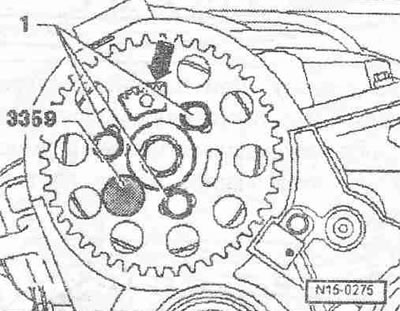
Screw in bolts "1" not all the way. Fix the camshaft bushing with lock "3359". Install in reverse order, while it is necessary to install the cylinder head cover. Install the toothed belt (adjust valve timing): toothed belt drive with hydraulically damped tension roller, toothed belt drive with friction-damped tension roller.
Instructions. Follow the instructions for removing and installing the toothed belt. The hoses and hose nipple of the air boost system must be cleaned of oil and grease before installation. Do not use lubricants under any circumstances.
Install the torsional vibration damper. Install the poly V-belt. Install the engine mount together with the bracket. Install the catalytic converter. Install the air ducts in the clamps. Electrical connectors and their gasket. Observe safety precautions after connecting the battery. Install the wiper arm. Change the oil. Change the coolant.
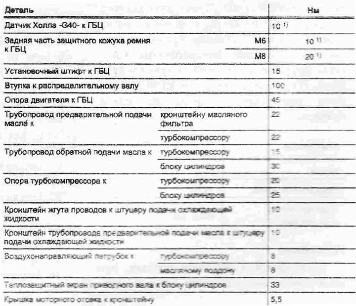
Tightening torques
[Information obtained from this resource Audimanual.ru]