
Instructions: Make sure that the camshaft bearing shells that have already been used are not mixed up (take into account the markings).
Make sure that the pushers are not mixed up; to do this, mark the back side with a waterproof marker.
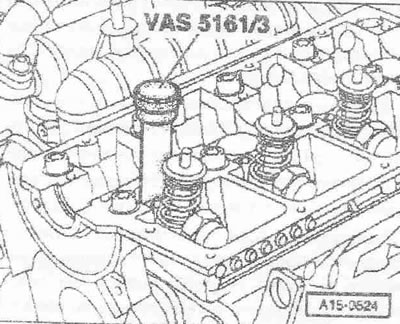
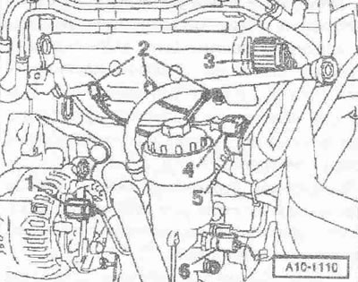
Remove the pushers from the guides. Place the pushers in the order they were removed on a clean mat with the working surface facing down. Insert the punch "VAS 5161/3" into the pushrod guide. Knock out the tightly seated crackers of all valves with a plastic hammer. Disconnect the plug connectors "2" of the glow plugs. Disregard other "pos.".
Unscrew all glow plugs using a SW 10 "3220" articulated wrench. Set the piston of the corresponding cylinder to "bottom dead center".
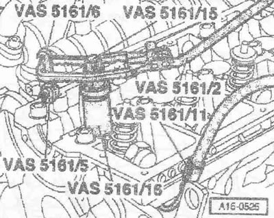
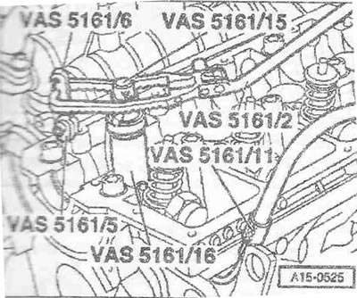
Screw the adapter in by hand "VAS 5161/11" into the appropriate glow plug socket. Screw in the universal hook "VAS 5161/6" with a fork (MB) "VAS 5161/5" into the threaded hole of the cylinder head. Insert the guide sleeve "VAS 5161/16" until it stops in the guide of the removed valve pusher. Mounting position of the guide sleeve: the ribbed surfaces are located transversely to the direction of movement. Insert the mounting cartridge "VAS 5161/15" into the guide bushing. Attach the adapter "VAS 5161/11" using a standard intermediate piece to the compressed air supply hose.
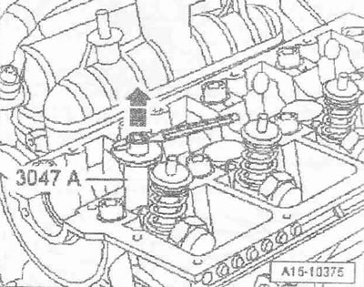
Minimum pressure: 6 bar overpressure. Install the fork "VAS 5161/2" on a universal hitch "VAS 5161/6" and press the mounting chuck downwards. At the same time, turn the knurled bolt with the mounting chuck head to the right until the ends enter the valve pins. Slightly turn the knurled bolt with the head back and forth, due to this the valve pins are unclenched and captured by the chuck. Release the pressure fork. Remove the mounting chuck. Remove the guide sleeve, valve spring plate and valve springs. Press out the "arrow" pin of the "3047 A" puller with a punch and remove the striker.
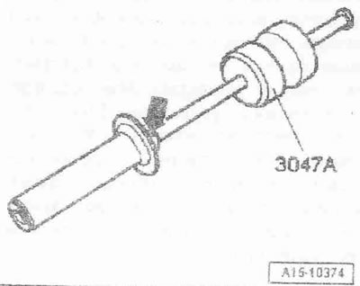
Place the lower part of the puller "3047 A" on the oil seal. Fix the puller "3047 A" with a punch or a tool for cotter pins, as shown in the figure. Install the mounting lever on the puller "3047 A" and remove the oil seal arrow-.
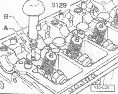
The new valve stem seals come with a plastic sleeve "A". Place the plastic sleeve "A" on the valve stem to prevent damage to the new valve stem seal "B". Lightly oil the working edge of the valve stem seal. Place the valve stem seal on the plastic sleeve. Carefully press the valve stem seal using the valve stem seal installation tool "3129" onto the valve guide. Remove the plastic sleeve.
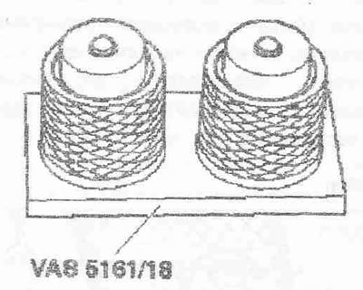
If the valve crackers have been removed from the mounting cartridge, they must first be inserted into the mounting fixture "VAS 5161/18". The larger diameter of the valve pin points upward.
Insert the valve springs, valve spring retainer and guide bushing "VAS 5161/16". Press down from above with the mounting chuck "VAS 5161/15" onto the mounting device and secure the valve crackers. Insert the mounting cartridge "VAS 5161/15" into the guide bushing "VAS 5161 /16". Press down on the push fork and pull up on the knurled bolt, turning it right and left, the valve crackers will be inserted. Unload the push fork with the knurled bolt still pulled out. Install the tappets. Install the camshaft. Install the glow plugs.
Instructions. After installing the camshaft, the engine must not be started for about 10 minutes. The hydraulic tappets must be settled (otherwise the valves will touch the pistons). After working on the valve mechanism, turn the engine by hand at least 2 revolutions to ensure that none of the valves are in contact with the piston.
(The original article is posted on the resource: audimanual.ru)