Repair Chevrolet Repair Toyota Repair Honda Repair AvtoVAZ Repair Mercedes-Benz Repair BMW Repair Opel
Home  |  Contacts  |  Sitemap  |    
English Русский
Български
Беларускі
Український
Српски
Hrvatski
Română
Polski
Slovenský
Magyar
AudiManual.ru


  • AUDI 80
  • AUDI 100
  • AUDI A3
  • AUDI A4
  • AUDI A6
  • AUDI A8
  • AUDI Q
  • OTHER
  • ARTICLES
A2 (1999-2005)

Removal and installation the balance shaft and crankshaft frame (Audi A2)

  • Home
  • Audi
  • A2 (1999-2005)
  • Engine 1.4 l (diesel)
  • Engine repair
  • Removal and installation the balance shaft and crankshaft frame
            0
Table of contents: Removal ↓ Installation ↓

Removal


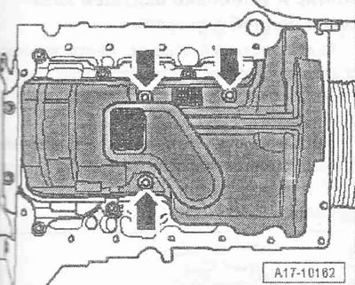
Remove the poly V-belt. Remove the toothed belt: toothed belt drive with hydraulically damped tension roller, toothed belt drive with friction-damped tension roller. Remove the oil pan. Remove the sealing flange from the belt pulley side. Unscrew the bolts "arrows". Unlock the 5 fastening brackets and remove the oil separator.

Press in the chain tensioner and secure it with the «T10060 A» lock «arrow». Unscrew the…


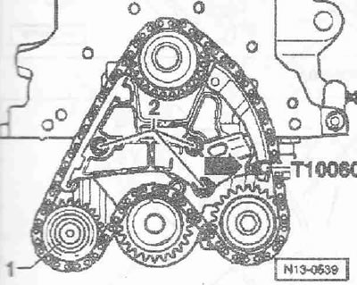
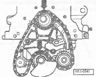
Press in the chain tensioner and secure it with the "T10060 A" lock "arrow". Unscrew the intermediate sprocket "1" from the crankshaft frame. Unscrew the bolt "2" and remove the chain tensioner. Remove the chain from the sprockets and place it on a clean mat.

Lock the balance shaft with a spanner SW 24/27 «pos. 1» as shown in the figure. The spanner must be…


Lock the balance shaft with a spanner SW 24/27 "pos. 1" as shown in the figure. The spanner must be aligned with the center of the balance shaft counterweight and is perpendicular to the balance shaft. Loosen the bolt "2" of the counterweight using the spanner "T10061". Only loosen the bolts, do not unscrew them.


Unscrew the crankshaft frame «3» from the cylinder block and remove it together with the balance…


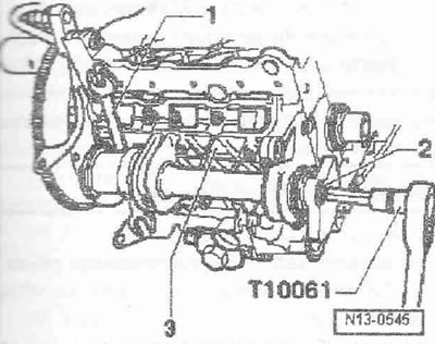
Unscrew the crankshaft frame "3" from the cylinder block and remove it together with the balance shaft. Place the crankshaft frame on a clean mat. Unscrew the counterweight bolt and remove the counterweight and sprocket. Turn the balance shaft so that it can be removed from the support.

Installation


Installation is in the reverse order, in this case it is necessary to replace the O-ring. Replace the bolts, which are additionally tightened to the appropriate angle. Lubricate the working surfaces of the support with oil and insert the balance shaft. Install the sprocket and counterweight on the balance shaft. The sprocket and counterweight can only be installed in one position. Tighten the counterweight and sprocket bolt by hand. Before installing the crankshaft frame, check the installation of the centering bushings in the cylinder block and the installation of the O-ring in the crankshaft frame. Screw the crankshaft frame "3" to the cylinder block by hand and align it. The crankshaft frame must be flush with the outer edge of the cylinder block on the belt pulley side. Screw the crankshaft frame crosswise in several stages. Lock the balance shaft with a SW 24/27 spanner "pos. 1", as shown in the figure. The spanner must be aligned with the center of the balance shaft counterweight and is perpendicular to the balance shaft. Tighten the counterweight with a new bolt "2". Install the chain tensioner. Clean the chain with a rag. Check that the "arrow" mark is located on top of the crankshaft sprocket.


Install the chain on the crankshaft, oil pump and balance shaft sprockets. The markings on the…


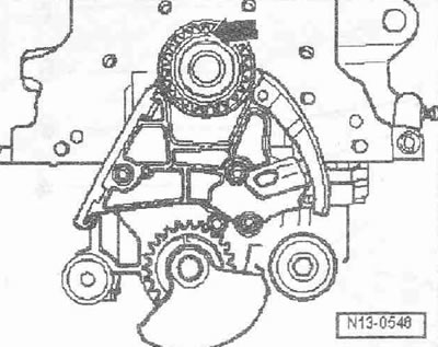
Install the chain on the crankshaft, oil pump and balance shaft sprockets. The markings on the crankshaft and balance shaft sprockets must match the chain links marked with a colored marker "arrows".

Instructions: The chain links marked with a colored marker should be additionally marked with a zigzag.


Insert the intermediate sprocket into the chain and screw it to the crankshaft frame. Remove the…


Insert the intermediate sprocket into the chain and screw it to the crankshaft frame. Remove the lock from the chain tensioner.

Check that the markings on the crankshaft and balance shaft sprockets match the chain links marked…


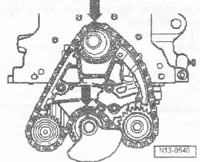
Check that the markings on the crankshaft and balance shaft sprockets match the chain links marked with a colored felt-tip pen "arrows". Install the sealing flange on the belt pulley side. Install the oil separator with a new sealing ring, to do this: lubricate the sealing ring with oil, lubricate the inner rod of the oil separator with oil, check the correct installation of the sealing tape, make sure that the oil separator snaps into the crankshaft frame. Install the oil pan. Install the toothed belt (adjust valve timing): toothed belt drive with hydraulically damped tension roller, toothed belt drive with friction-damped tension roller. Install the poly V-belt.


Tightening torques:
  • Crankshaft frame with balance shaft to cylinder block: 14 Nm + 180° 1)
  • Counterweight with sprocket to crankshaft frame: 100 Nm + 90° 1)
  • Chain tensioner to crankshaft frame: 8 Nm + 90° 1)
  • Intermediate sprocket to crankshaft frame: 20 Nm
  • Oil separator to crankshaft frame: 5 Nm

1) Replace the bolts.
The article was checked by auto expert Daniil Ushakov
This article is available at russian, bulgarian, belarusian, ukrainian, serbian, croatian, romanian, polish, slovak, hungarian

Share information:
Previous articles
Audi A2: Engine repair
Next articles

Balance shaft and crankshaft frame — design description
Removal and installation the sealing flange from the gearbox side
Removal and installation a dual mass flywheel
Removal and installation the sealing flange on the belt pulley…
Crankshaft — design description
Removal and installation the crankshaft sprocket
Checking the protrusion of the dowel pin from the crankshaft
Removal and installation the drive sprocket of the chain drive


Similar articles on other Audi car models:
Intermediate shaft — removal, inspection and installation Audi 80 B3 (1986-1991, petrol)
Removal, inspection and installation of the crankshaft Audi 100 C3 (1982-1990)
Removal and installation the shield and beam of the side… Audi A3 Type 8L (1996-2003)
Removal and installation the drive shaft Audi A4 B6 (2000-2006)
Removal and installation the drive shaft Audi A6 C5 (1997-2004)
Removal and installation the outer joint of the drive shaft Audi A8 D2 (1994-2002)
Removal and installation of timing chains, balance shaft and… Audi Q7 Typ 4L (2005-2015, diesel)
Link to this page in different formats


Visitor comments

No comments yet


How much will 22 + 25 =


Audi A2(1999-2005) 
  • General information
  • Introduction to the guide
  • Maintenance
  • Engine 1.4 l (gasoline)
  • Engine repair
  • Lubrication system
  • Cooling system
  • Exhaust system
  • Engine 1.6 l (gasoline)
  • Engine repair
  • Lubrication system
  • Cooling system
  • Exhaust system
  • Engine 1.2 l (diesel)
  • Engine repair
  • Lubrication system
  • Cooling system
  • Injection and turbocharging
  • Engine 1.4 l (diesel)
  • Engine repair
  • Lubrication system
  • Cooling system
  • Turbocharging system
  • Supply system
  • Fuel injection system
  • Exhaust system
  • Transmission
  • Mechanical gearbox 02J
  • Mechanical gearbox 02T
  • Mechanical gearbox 085 DS
  • Chassis
  • Car suspension
  • Steering
  • Brake system
  • Body
  • Exterior
  • Interior
  • Seats
  • Doors, locks and windows
  • Safety system
  • Heating and air conditioning
  • Electrical equipment
  • Power devices
  • Equipment and devices
  • Wipers and washers
  • Lighting and lamps
  • Breakers and switches
  • Electrical circuits
 
AudiManual.ru © 2017-2026 · Mobile version · Feedback · Sitemap: EN BG BY UA RS HR RO PL SK HU · Site search · News and articles
80 B2 · 80 B3 petrol · 80 B3 · 80 B4 · 100 C3 diesel · 100 C3 petrol · 100 C3 · 100 C4 petrol · 100 C4 · A3 Type 8L · A4 B5 petrol · A4 B5 · A4 B6 petrol · A4 B6 · A4 B7 · A4 B8 · A6 C4 · A6 C5 · A6 C5 Allroad · A8 D2 · Q5 Type 8R · Q7 Typ 4L · Audi A2 ·
This site uses cookies 🍪. Click the button to accept this fact.