
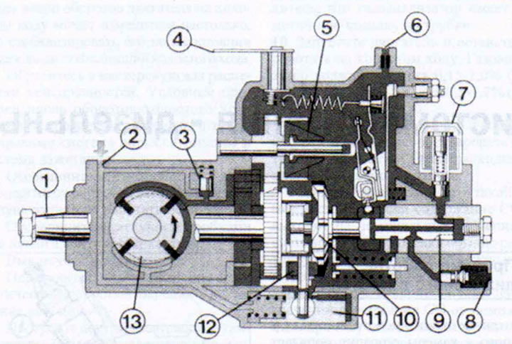
2.0 High pressure fuel pump in section
1 - drive shaft
2 - fuel inlet channel
3 - safety valve
4 - accelerator cable mounting lever
5 - centrifugal regulator
6 - return hole
7 - fuel cut-off valve
8 - high pressure fuel line
9 - distribution piston 10 - disc cam
11 - fuel injection advance clutch (rotated 90° for better visibility)
12 - pusher roller
13 - vane pump (also rotated 90°)
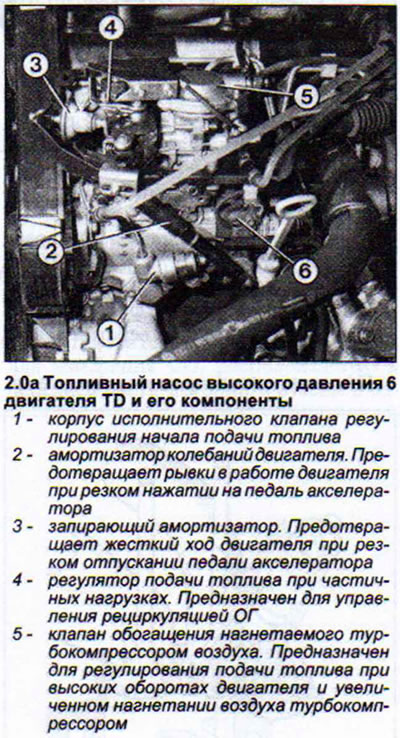
TD engines have distributor-type fuel injection pumps, which are also more durable (see illustration 2.0a).
Attention! The distribution fuel injection pump is particularly sensitive to impurities and contamination of the fuel (water, dirt), which clog the pump hole. Subsequent repair of the fuel injection pump is very expensive, because it needs to be tested on a bench. For this reason, we recommend changing the fuel filter regularly, as well as draining the accumulated condensate in a timely manner.
A component of the high-pressure fuel pump is a vane fuel pump, which takes fuel from the pipeline from the fuel filter. The vane pump impeller, rotating when the engine is running, squeezes fuel into the body of the high-pressure fuel pump itself to the distributor piston. The piston is the main part of the high-pressure fuel pump and in its function resembles the ignition distributor of a gasoline engine.
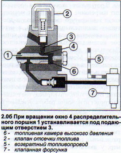
The distribution piston has a large number of holes and recesses, which helps it perform its function: to take in fuel and inject it. During the fuel intake stroke, the piston window is positioned opposite the feed hole (see illustration 2.0b).
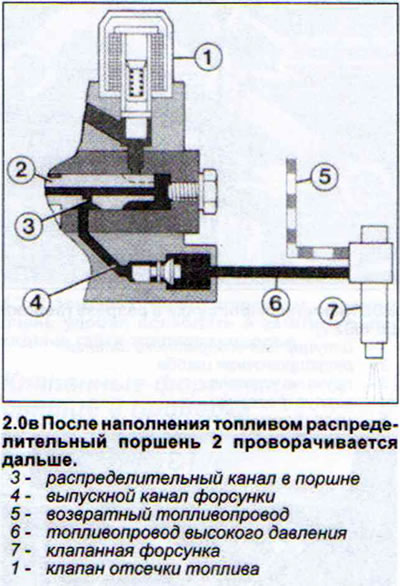
The fuel pumped by the vane pump enters the receiving chambers of the distribution piston. After this, the piston is rotated by a toothed belt from the crankshaft and the feed hole is closed. Now the next two elements of the high-pressure fuel pump come into action. The distribution piston is connected to a disc cam, which begins to move towards the roller tappet. As soon as the projections of the disc cam reach the rollers of the tappet, the disc cam together with the distribution piston are pressed back. This happens at the moment when the distribution channel in the piston coincides with the outlet channel of the valve injector and the fuel goes to the cylinder, in the combustion chamber of which everything is ready to receive and ignite it. The distribution piston moves further back and fills up again. After this, the cycle is repeated, and the fuel is injected into the next cylinder (see illustration 2.0v).
Before the fuel reaches the feed port and gets into the distribution piston chamber of the high-pressure fuel pump, it must pass through the electromagnetic fuel shut-off valve. The fuel shut-off valve is activated when the ignition key is turned to the first position and opens the way for the fuel. When the ignition is turned off, the power supply to the valve is disconnected and it closes the fuel supply channel.
Considering that during movement there is a frequent change of engine loads, then to take them into account and provide the engine with fuel according to its current load, the high-pressure fuel pump has a centrifugal regulator. The regulator weights, depending on the engine speed, are more or less mixed outward and at the same time press on the regulating valve, which opens the outlet hole in the distribution piston and thus diverts some of the fuel.
At the moment of starting, the outlet hole is closed and the engine receives the maximum volume of fuel. However, this position is maintained only until the idle speed reaches the nominal value. From this moment, the fuel supply is regulated.
The injection pump behaves similarly in full and partial load mode. The maximum engine speed is also limited by the centrifugal governor. As soon as the engine speed reaches over 5200+100 rpm, the outlet opening is fully opened and the engine is unable to increase speed.
As the engine speed increases, fuel injection must be carried out ahead of time so that the mixture ignites in a timely manner. An earlier injection is provided by a fuel injection advance clutch. As the engine speed increases, the rotation speed of the vane pump increases and the fuel pressure increases. This was used to advance the injection. Under the fuel pressure, the spring is compressed and the piston is pressed back, which shifts the roller tappet around its axis. The stops of the disc cam reach the tappet rollers faster and the fuel is injected earlier. As the speed drops, the clutch piston moves back, and with it the roller tappet.
The pump's start of delivery varies depending on the engine load. The injection pump recognizes the engine load as follows:
- the accelerator pedal is pressed and the engine speed is low - high load;
- the accelerator pedal is released and the engine speed is high (forced idle on descent) = no load on the engine.
When the engine load increases, the injection pump starts to supply fuel ahead of schedule, and when the load is low, it starts to supply fuel more slowly.
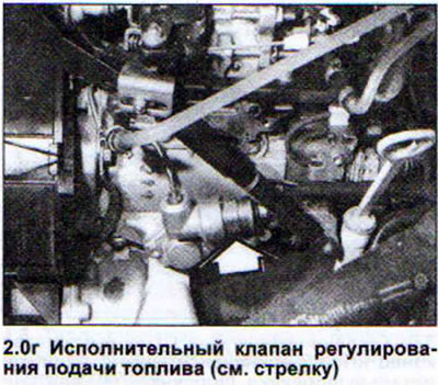
Starting from 2/92, the high-pressure fuel pump is equipped with an actuator valve for regulating the start of fuel supply, which switches off the regulation of fuel supply depending on the engine load when it reaches over 3000 rpm. This helps to reduce the content of harmful substances in the fuel, and also to some extent reduces fuel consumption (see illustration 2.0g). The exhaust gas recirculation control unit controls the actuator valve.
(The original material is located on the website AUDImanual.ru)