
Repair Chevrolet Repair Toyota Repair Honda Repair AvtoVAZ Repair Mercedes-Benz Repair BMW Repair Opel
Home  |  Contacts  |  Sitemap  |    
English Русский
Български
Беларускі
Український
Српски
Hrvatski
Română
Polski
Slovenský
Magyar
AudiManual.ru


  • AUDI 80
  • AUDI 100
  • AUDI A3
  • AUDI A4
  • AUDI A6
  • AUDI A8
  • AUDI Q
  • OTHER
  • ARTICLES
B4 (1991-1996) B3 (1986-1991) B3 (1986-1991, petrol) B2 (1979-1986)

Sensors of the fuel system of diesel engines TDI (Audi 80 B4)

  • Home
  • Audi 80
  • B4 (1991-1996)
  • Power unit
  • Diesel fuel system
  • Sensors of the fuel system of diesel engines TDI
            0
Table of contents: Accelerator Pedal Position Sensor ↓ Engine speed and TDC sensor ↓ Air flow meter ↓ Air mass flow meter ↓ Intake Manifold Pressure Sensor ↓ Fuel filter condensate level sensor ↓ Boost pressure valve ↓ EGR valve ↓ Preheating device ↓

Accelerator Pedal Position Sensor


TDI engines do not have an accelerator cable. The potentiometer transmits information about the accelerator pedal position to the control unit. To prevent the control unit from making incorrect decisions (for example, if a defect causes the unit to believe that the pedal is in the "Full Accelerator" position), the brake pedal is connected to an additional brake light switch, which prevents the control unit from recognizing the "Full Accelerator" information when braking. The same applies to the clutch pedal.

Engine speed and TDC sensor


This inductive sensor is located under the oil filter flange on the crankcase and reads the number of revolutions from the contact ring on the crankshaft. The contact ring has 4 grooves, each of which corresponds to TDC (see illustration 10.0a).
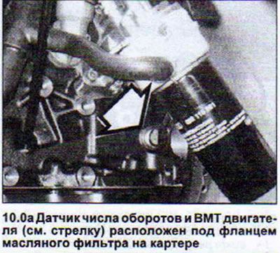
This inductive sensor is located under the oil filter flange on the crankcase and reads the number…


Needle lift sensor in cylinder #3 injector.


This sensor informs the control unit of the exact start of injection at the current moment (see illustration 10.0b).
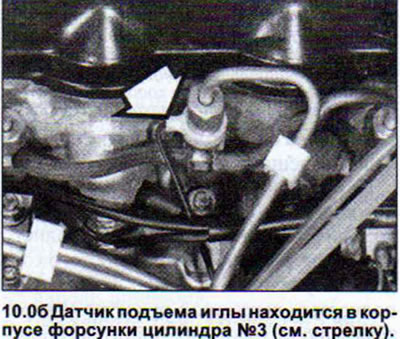
This sensor informs the control unit of the exact start of injection at the current moment (see…


Intake air temperature, intake manifold temperature, coolant temperature and fuel temperature sensor

These sensors are located in the air flow meter, in the air guide pipe, in the coolant outlet pipe and in the high-pressure fuel pump itself (see illustration 10.0b).
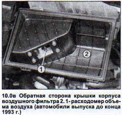
These sensors are located in the air flow meter, in the air guide pipe, in the coolant outlet pipe…


Air flow meter


Information about the amount of air admitted is needed by the control unit to calculate the fuel required for injection. The measurement of the volume of incoming air occurs as follows. The valve shutter of the air flow meter deflects depending on the incoming air volume. This movement of the shutter is recorded as a change in resistance (potentiometer) and is recognized by the control unit as an electric current value (see illustration 10.0g).
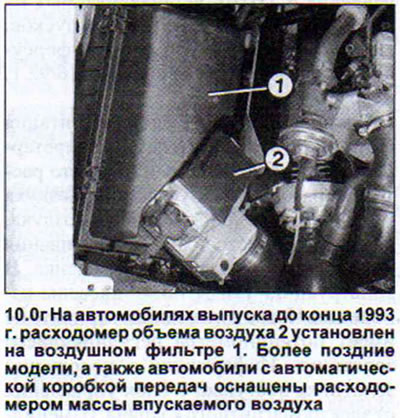


Information about the amount of air admitted is needed by the control unit to calculate the fuel…


Air mass flow meter


This sensor is installed on cars manufactured since the end of 1993, as well as on cars with an automatic transmission. It performs the same function as the air flow meter, which it replaces, but the measurement is performed differently. A film installed in the air flow path is heated. Depending on its mass, the incoming air cools this film to a greater or lesser extent. The film resistance changes and the control unit again receives an electrical signal of a certain value.

Intake Manifold Pressure Sensor


This sensor is located at the rear of the engine compartment on the right side and is connected by a hose to the charge air cooler (intercooler). In cars with automatic transmission and in cars with manual transmission produced since the end of 1993, this sensor is an element of the control unit. The specified sensor is responsible for information about the boost pressure and regulation of the injection volume.

Fuel filter condensate level sensor


This sensor is not installed on vehicles with automatic transmission. Vehicles with manual transmission were equipped with this sensor until the end of 1993. (see illustration 10.0d).
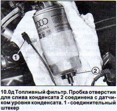


This sensor is not installed on vehicles with automatic transmission. Vehicles with manual…


Boost pressure valve


The boost pressure is regulated by an electromagnetic valve that opens a pressure-reducing valve. In earlier cars, it is located at the rear of the engine compartment. In cars with an automatic transmission, as well as in cars with a manual transmission produced since the end of 1993, it is located on the right in the front of the engine compartment.

EGR valve


The exhaust gas recirculation valve together with the oxidation catalyst ensures that the content of harmful substances in the exhaust gas is within the existing standards and requirements. Unlike the 55 kW diesel engine with swirl chamber injection, in which the exhaust gas recirculation is carried out according to the "Inlet-Outlet" principle, in TDI engines intermediate exhaust gas values can be produced using recirculation.

Preheating device


The injection system control unit controls the preheating device depending on the engine temperature.
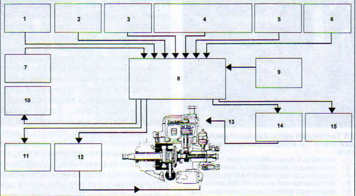
10.0 Operation diagram of the control unit of the fuel system of diesel engines TDI. The arrows…

10.0 Operation diagram of the control unit of the fuel system of diesel engines TDI. The arrows show the incoming and outgoing information
1 - accelerator pedal
2 - engine speed and TDC
3 - start of injection
4 - temperature of intake air, coolant and fuel
5 - boost pressure
6 - boost air temperature
7 - air flow meter
8 - electronic control unit
9 - other information
10 - EGR valve
11 - start of injection
13 - position of the control valve
14 - injection volume
15 - glow plug control
The article was checked by auto expert Timur Bazhenov
This article is available at russian, bulgarian, belarusian, ukrainian, serbian, croatian, romanian, polish, slovak, hungarian

Share information:
Previous articles
Audi 80 B4: Diesel fuel system
Next articles

Power supply system — TDI diesel engines
Idle speed — check
Cold Start Accelerator Cable — Removal and Adjustment
Accelerator cable — removal and adjustment
Fuel injection system of TDI engines — check
TD Engine Preheating System
TD Engine Preheating System — Check
TDI engine preheating system


Similar articles on other Audi car models:
Possible malfunctions of the diesel fuel system Audi 100 C4 (1990-1994)
Checking the fuel system Audi A3 Type 8L (1996-2003)
Scheme 4. Direct fuel injection system of diesel engines Audi A4 B5 (1994-2001)
General information about the fuel system of diesel engines Audi A6 C5 Allroad (1999-2005)
Pre-heating system for diesel engines Audi A8 D2 (1994-2002)
Removal air from the fuel system Audi Q5 Type 8R (2008-2017)
Fuel injection system relays and sensors Audi A2 (1999-2005)
Link to this page in different formats


Visitor comments

No comments yet


How much will 20 + 21 =


80(B4, 1991-1996) 
  • General information
  • User manual
  • Maintenance
  • Troubleshooting
  • Power unit
  • Engine
  • Cooling system
  • Heating and ventilation
  • Petrol injection
  • Diesel fuel system
  • Fuel system
  • Exhaust systems
  • Ignition system
  • Transmission
  • Clutch
  • Car gearbox
  • Chassis
  • Brake system
  • Suspension and steering wheel
  • Body
  • Body and trim
  • Electrical equipment
  • Electrical system
  • Electrical circuits
 
80(B3, 1986-1991) 
  • General information
  • Repair characteristics
  • Maintenance
  • Power unit
  • Gasoline engine
  • Diesel engine
  • Engine lubrication system
  • Fuel system (gasoline)
  • Injection system (gasoline)
  • Fuel system (diesel)
  • Ignition system
  • Cooling system
  • Heater
  • Exhaust system
  • Transmission
  • Clutch and gearbox
  • Chassis
  • Steering
  • Brake system
  • Car suspension
  • Body
  • Body elements
  • Electrical equipment
  • Power devices
  • Lighting and appliances
  • Electrical circuits
 
80(B3, 1986-1991, petrol) 
  • General information
  • User manual
  • Maintenance
  • Power unit
  • Engine 4-cylinder
  • Engine 5-cylinder
  • Cooling system
  • Fuel and exhaust systems
  • Ignition system
  • Transmission
  • Clutch
  • Mechanical transmission
  • Automatic transmission
  • Drive shafts
  • Chassis
  • Brake system
  • Suspension
  • Steering
  • Body
  • Exterior
  • Interior
  • Electrical equipment
  • Equipment and devices
  • Electrical circuits
 
80(B2, 1979-1986) 
  • General information
  • User manual
  • Power unit
  • Engine FZ
  • Engine EP, YP, YZ, DT, DS, DZ
  • Transmission
  • Clutch
  • 4 speed gearbox
  • 5 speed gearbox
  • Front wheel drive
  • Chassis
  • Front suspension
  • Rear suspension
  • Steering
  • Brake system
  • Electrical equipment
  • Equipment and devices
  • Electrical circuits
 
AudiManual.ru © 2017-2026 · Mobile version · Feedback · Sitemap: EN BG BY UA RS HR RO PL SK HU · Site search · News and articles
80 B2 · 80 B3 petrol · 80 B3 · 80 B4 · 100 C3 diesel · 100 C3 petrol · 100 C3 · 100 C4 petrol · 100 C4 · A3 Type 8L · A4 B5 petrol · A4 B5 · A4 B6 petrol · A4 B6 · A4 B7 · A4 B8 · A6 C4 · A6 C5 · A6 C5 Allroad · A8 D2 · Q5 Type 8R · Q7 Typ 4L · Audi A2 ·
This site uses cookies 🍪. Click the button to accept this fact.