
Table of contents: Temperature sensors ↓ Injector needle lift sensor ↓ Engine speed and TDC sensor ↓ Intake Manifold Pressure Sensor… ↓ Accelerator Pedal Position Sensor ↓ Injection start sensor ↓ Fuel supply regulator ↓ Fuel cut-off valve ↓
The electronic control unit of the fuel injection system of TDI engines can recognize and register 21 faults of the injection and engine heating system components. At the same time, the unit distinguishes between faults of a permanent nature and random faults that have manifested themselves once. One-time faults are deleted from the unit's memory after 40 engine starts. Faults that affect the car's behavior during a trip are signaled by control lights on the instrument panel. The car owner is not able to personally interrogate the self-diagnostic unit and print out the registered faults. This operation is performed in a workshop using the VAG 1551 device.
Checking the fuel injection system requires the presence of rather complex and expensive control and measuring devices. For this reason, the car owner cannot independently perform most types of system checks. At the same time, the car owner can perform some checks on his own.
The injection system control unit cannot be checked using the devices that a car enthusiast has at his disposal. As practice shows, the control unit is rarely the cause of engine failure. All sorts of sensors and switches cause much more problems.
1. Make sure that fuses 21 and 27 of the fuel injection system are normal.
2. Check the surge protection relay on the auxiliary relay box on the left under the instrument panel.
3. Check the fuel system.
4. Inspect all parts of the fuel injection system and especially the condition and fastening of the fuel hoses.
5. Check the condition and tightness of all air supply hoses. If the hose is not tight, additional air is sucked in, which is not taken into account by the system.
6. Inspect the connector plugs. The sensitive contacts of the plugs should not be broken or bent. They must not be cleaned. To increase conductivity, spray the contacts with an aerosol composition for plug contacts.
If the source of the fault is not found, then check the operation of all system components in order. We recommend that you contact a workshop to print out the faults registered by the self-diagnosis system before checking the system components. This should be done before disconnecting the battery.
Caution! Before disconnecting any connector of the injection system, switch off the ignition. Otherwise, when disconnecting the connector, voltage peaks may occur that are dangerous for the control unit.
If the power supply system is completely inoperative, first check fuses No.21 and 27, as well as the overvoltage protection relay.
Temperature sensors
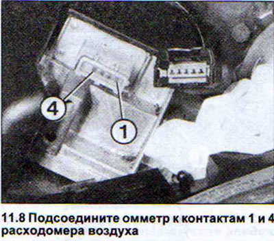
7. Disconnect the intake air temperature sensor multi-pin connector on the air flow meter.
8. Connect an ohmmeter to terminals 1 and 4 of the air flow meter (see illustration).
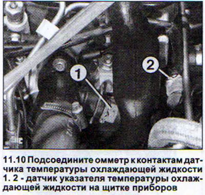
9. Disconnect the coolant temperature sensor plug.
10. Connect an ohmmeter to the coolant temperature sensor terminals (see illustration).
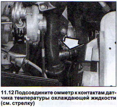
11. Disconnect the intake manifold temperature sensor plug. The sensor is located in the front right side of the engine compartment in the air guide pipe of the intercooler and intake manifold.
12. Connect the ohmmeter to the sensor contacts (see illustration).
13. Disconnect the round plug on the rear wall of the engine compartment. This is the plug connector for the fuel injection pump power wires.
14. Connect an ohmmeter to contacts 5 and 6, through which power is supplied to the fuel temperature sensor.
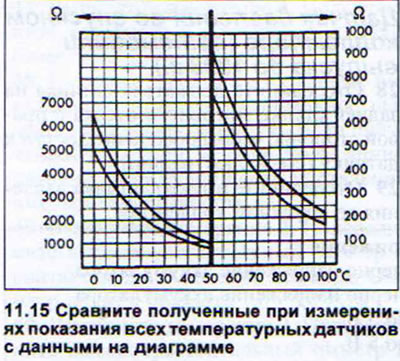
15. Compare the readings obtained from all temperature sensors with the data on the diagram. The values obtained for the sensors at the current moment should be within the wide curve on the diagram (see illustration). If so, then the sensors are normal.
Air flow meter (cars with manual transmission produced before the end of 1993.)
16. Release the multi-pin connector on the air flow meter by sliding the rubber cuff. Do not disconnect the connector itself (see illustration).
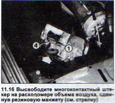
Contacts are numbered from right to left from 5 to 1.
17. Connect a voltmeter to contacts 2 and 3 to check the power supply.
18. Turn on the ignition and read the voltmeter reading. The nominal value is about 5 V. If this value is not reached, there is a fault on the flow meter power line from the control unit.
19. Connect a voltmeter to check the flow meter potentiometer signal to terminals 2 and 4.
20. Start the engine and read the voltmeter reading. At idle, the signal voltage should be 0.5-1.5 V.
21. Increase the RPM and monitor the voltmeter readings. The signal voltage should increase as the RPM increases. The maximum value of 4.5 V is reached at maximum engine RPM. If the potentiometer signal voltage does not increase proportionally to the engine RPM or if it drops, the air flow meter is faulty.
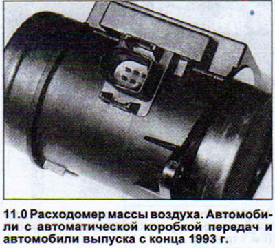
Air mass flow meter (cars produced since the end of 1993.)
These measurements only apply to vehicles with automatic transmission and vehicles produced since the end of 1993, when serial equipment with the new generation fuel injection system began.
The air mass flow meter can only be checked in a workshop. A car enthusiast can only check the incoming signals (see illustration 11.0).
22. Disconnect the air mass meter plug.
23. Check the voltage at the plug contacts with the ignition on (see illustration).
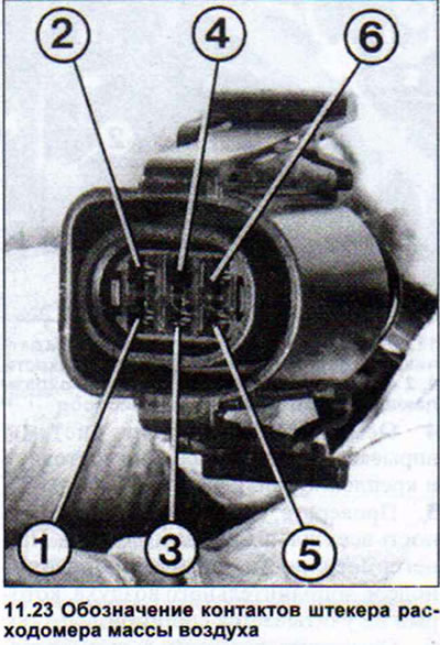
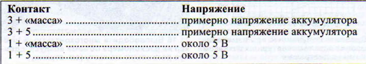
The table below shows the nominal values that should be obtained when measuring the voltage at the contacts of the air mass meter plug. If the obtained values are less than the specified ones, check the power supply wires of the control unit or the power supply to the unit.
Injector needle lift sensor
24. Disconnect the sensor plug on the rear wall of the engine compartment (see illustration).
25. Connect a high-precision ohmmeter to the plug contacts. The ohmmeter readings should be 90-110 ohms. If the readings obtained are outside the specified values, the injector needle lift sensor must be replaced.
Engine speed and TDC sensor
26. Disconnect the sensor plug on the rear wall of the engine compartment.
27. Connect a high-precision ohmmeter to the plug contacts. The ohmmeter reading should be approximately 1 kOhm. If this is not the case, the engine speed and TDC sensor must be replaced.
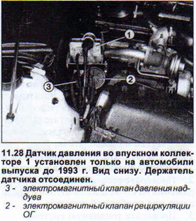
Intake Manifold Pressure Sensor (cars produced before 1993.)
28. Disconnect the sensor holder on the rear wall of the engine compartment on the right side to provide access to the sensor (see illustration).
29. Disconnect the intake manifold pressure sensor connector.
30. Connect a voltmeter to both side contacts going to the sensor.
3.1 Turn on the ignition and read the voltmeter readings. The nominal value is approximately 5 V. If the voltmeter shows a lower value, then there is a fault on the sensor power line from the control unit.
32. Connect the plug and move the rubber cuff covering the plug.
33. Connect the plug to the released contacts, to which the wires with brown-white and yellow-white insulation lead.
34. Start the engine and slowly increase its speed. At the same time, the voltage registered by the voltmeter should also increase. If the voltmeter needle does not move, then the pressure sensor in the intake manifold is faulty.
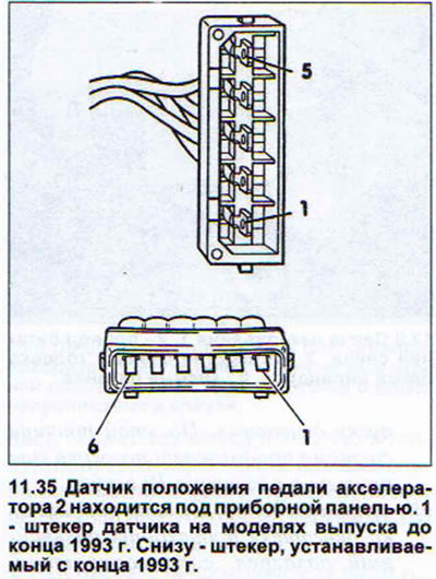
Accelerator Pedal Position Sensor
35. Remove the trim in the driver's footwell under the dashboard (see illustration).
36. Disconnect the accelerator pedal position sensor connector.
37. Connect a high-sensitivity ohmmeter to the following sensor terminals:
- to terminals 1 and 3. The ohmmeter should show 0.8-1.4 kOhm
- to terminals 2 and 3. The ohmmeter should show 0.8-1.4 kOhm
- to terminals 4 and 3 (only cars with manual transmission produced before the end of 1993.). When the accelerator pedal is released, the ohmmeter should show 0.8 - 1.2 kOhm, and when it is fully pressed, the infinity sign.
- to terminals 4 and 6 (only cars with manual transmission produced since the end of 1993 and cars with automatic transmission). When the accelerator pedal is released, the ohmmeter should show 0.8 - 1.2 kOhm, and when it is fully pressed, the infinity sign.
- to terminals 5 and 6 (only cars with automatic transmission). When the accelerator pedal is released, the ohmmeter should show 00 Ohms, and when it is fully pressed, 0.8 - 1.2 kOhms.
If the ohmmeter readings do not match those specified, the accelerator pedal position sensor is faulty and must be replaced.
Injection start sensor
38. Disconnect the sensor plug located on the high-pressure fuel pump (see illustration).
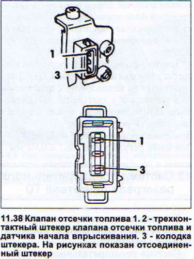
39. Connect a voltmeter to both side contacts 1 and 3 (see illustration 11.38).
40. Turn on the ignition and read the voltmeter reading. The nominal value is equal to the battery voltage (approximately 12 V). If the voltmeter reading is different, then there is a malfunction on the power line from the control unit side.
41. Connect a highly sensitive ohmmeter to the contacts of the connector block 2 and 3. It should register 14-18 Ohms. Otherwise, the fuel injection start sensor must be replaced.
Fuel supply regulator
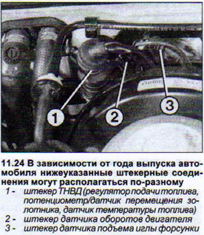
42. Disconnect the round multi-pin plug on the rear wall of the engine compartment (see illustration)
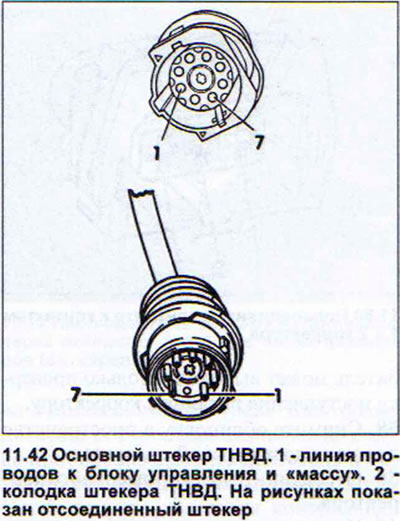
43. Connect the voltmeter to contact 7 of the wire line to the control unit and ground.
44. Turn on the ignition and read the voltmeter reading. The nominal value is equal to the battery voltage (approximately 12 V). If the voltmeter reading is different, there is a fault on the power line. Check the surge protection relay.
45. Connect a high-sensitivity ohmmeter to the following terminals of the plug connector:
- contacts 4 and 7 (cars with manual transmission produced before the end of 1993.);
- contacts 3 and 7 (cars with manual transmission produced since the end of 1993 and automatic transmission).
In both cases, the ohmmeter should show 0.4-1.1 Ohm. If the ohmmeter readings are outside the specified values, the fuel supply regulator must be replaced.
Potentiometer for moving the control valve. Cars with manual transmission manufactured before the end of 1993.
46. Disconnect the round multi-pin plug on the rear wall of the engine compartment (see illustration 11.42).
47. Perform measurement 1. Connect the voltmeter to contact 2 of the plug (ground).
48. Turn on the ignition and read the voltmeter reading. The nominal value is about 5 V. If the reading is less, there is a fault on the power supply line from the control unit side.
49. Perform measurement 2. Connect a high-sensitivity ohmmeter to contacts 2 and 3 of the plug connector. The ohmmeter should show 1.0-3.0 kOhm.
50. Perform measurement 3. Connect a highly sensitive ohmmeter to contacts 1 and 3 of the plug connector. The ohmmeter should show 0.5-2.0 kOhm.
If at least one of the obtained values is less than the specified ones, then the potentiometer must be replaced.
Spool valve displacement sensor (cars produced since the end of 1993.)
51. Disconnect the round multi-pin plug on the rear wall of the engine compartment (see illustration 11.42).
52. Perform measurement 1. Connect the voltmeter to contact 1 of the plug (ground).
53. Turn on the ignition and read the voltmeter reading. The nominal value is about 2.5 V. If the reading is less, there is a fault on the power supply line from the control unit side.
54. Perform measurement 2. Connect the voltmeter to contact 2 of the plug (ground).
55. Turn on the ignition and read the voltmeter reading. The nominal value is about 2.5 V. If the reading is less, there is a fault on the power supply line from the control unit side.
56. Perform measurement 3. Connect a highly sensitive ohmmeter to contacts 1 and 3 of the plug connector. The ohmmeter should show 4.9-7.5 kOhm.
57. Perform measurement 4. Connect a highly sensitive ohmmeter to contacts 2 and 3 of the plug connector. The ohmmeter should show 4.9-7.5 kOhm.
If at least one of the values obtained during the last two measurements is less than those specified, then the potentiometer must be replaced.
High-altitude fuel supply corrector. Cars with automatic transmission and cars produced since the end of 1993 with manual transmission. The corrector itself and its readings can only be checked in a workshop. A car enthusiast can only check the power supply to the corrector.
58. Remove the trim in the passenger side footwell.
59. Disconnect the altitude corrector plug.
60. Connect the voltmeter to contacts 1 and 2 of the corrector (see illustration).
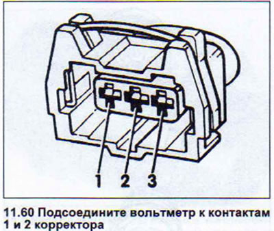
61. Turn on the ignition. The voltmeter should show approximately 5 V. Otherwise, there is a fault in the power supply wire.
Fuel cut-off valve
In order to stop the engine, the fuel shut-off valve closes the fuel supply to the injectors. If the fuel shut-off valve fails, the engine cannot be started. If the engine does not start, despite the fact that the fuel tank is full and the preheating system is normal, then the valve may be faulty.
62. First of all, make sure that the fuel cut-off valve power wire is normal.
63. Ask an assistant to turn the key in the ignition switch, and listen to see if the fuel shut-off valve is triggered. When triggered, the valve makes a fairly loud clicking sound. If there is no such sound, then the cause of the malfunction is the lack of power to the valve or in the valve itself.
64. Check the voltage supply to the valve. To do this, turn on the ignition and connect a tester with a diode lamp to the valve contact. If the lamp lights up, the valve itself is faulty. Otherwise, the power supply wire is faulty. Despite the valve malfunction or interruptions in its power supply, the trip can be continued.
65. Disconnect the wire from the fuel shut-off valve.
66. Unscrew the valve from the high-pressure fuel pump.
67. Remove the valve piston.
68. Screw the valve body back into place to ensure a tight seal for the system.
69. Start the engine. Starting will be done as usual, but you will need to turn off the engine with the gear engaged.
Checking the idle speed of TDI engines is only necessary if the system is defective. The electronic control unit automatically maintains the engine idle speed within 800-900 rpm.
Replacement of faulty injectors, as well as adjustment of the injection pump start, are performed on vehicles with a TDI engine in the same way as on TD engines. TD1 engines only have different settings and adjustment values:
The check value is 0.65 - 0.75 mm. The adjustment value is 0.7±0.02 mm.
This article was copied from an online resource: AUDImanual.ru