Repair Chevrolet Repair Toyota Repair Honda Repair AvtoVAZ Repair Mercedes-Benz Repair BMW Repair Opel
Home  |  Contacts  |  Sitemap  |    
English Русский
Български
Беларускі
Український
Српски
Hrvatski
Română
Polski
Slovenský
Magyar
AudiManual.ru


  • AUDI 80
  • AUDI 100
  • AUDI A3
  • AUDI A4
  • AUDI A6
  • AUDI A8
  • AUDI Q
  • OTHER
  • ARTICLES
B4 (1991-1996) B3 (1986-1991) B3 (1986-1991, petrol) B2 (1979-1986)

Technical characteristics of the contactless ignition system (Audi 80 B2)

  • Home
  • Audi 80
  • B2 (1979-1986)
  • Power unit
  • Engine EP, YP, YZ, DT, DS, DZ
  • Technical characteristics of the contactless ignition system
            0
Table of contents: Ignition distributor sensor ↓ Switch ↓ Ignition coil ↓ High voltage wires ↓
Since the 1980 model year, the YP, YZ engines, as well as the EP, DT, DS and DZ engines, were equipped with a contactless ignition system, including a distributor sensor with a built-in electronic control pulse sensor, an ignition coil and a switch.

Ignition distributor sensor


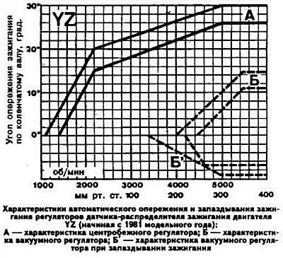
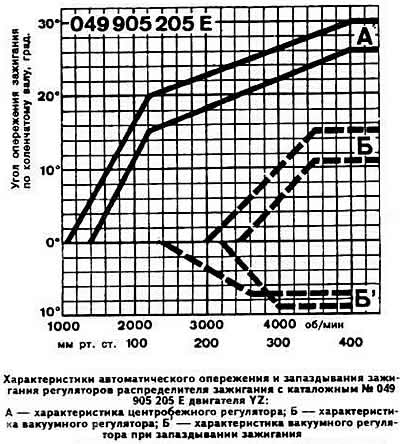
Bosch brand ignition distributor sensor, shielded, four-cylinder, with vacuum and centrifugal ignition timing regulators (the YP, YZ engine distributor sensor has a vacuum regulator for ignition advance and retardation), with high voltage current distributor with axial terminals, with built-in microelectronic sensor (generator) control pulses with a change in the phase angle of the resulting voltage. It is driven by a helical gear of the intermediate shaft. The direction of rotation is left (from the camshaft drive side). The voltage value generated by the generator sensor is within the range of 0-2 V. Resistance of the distributor rotor (marked "R1"), Ohm: 1000.

Note: Since July 1985, a speed limiter has been built into the rotor of the ignition distributor of OT and DS engines, which limits the engine speed to 6150-6450 rpm.


Ignition distributor sensor numbers according to the Bosch catalogue:
  • engines YP, YZ: 0 221 122 023;
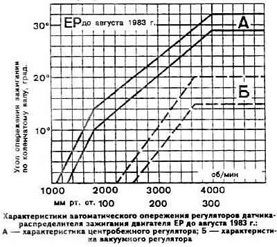
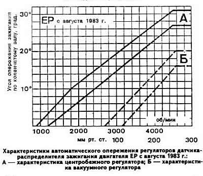
  • engine EP: 056 905 200 J (until August 1983.); 056 905 205 L (since August 1983.);
  • engine OT: 026 905 206 (until July 1985.); 026 905 206 AD (since July 1985.);
  • dS engine: 026 905 206 F (until July 1985.); 026 905 206 J (since July 1985.);
  • engine DZ. 026 905 206 A (until July 1985.); 026 905 205 AA (since July 1985.).

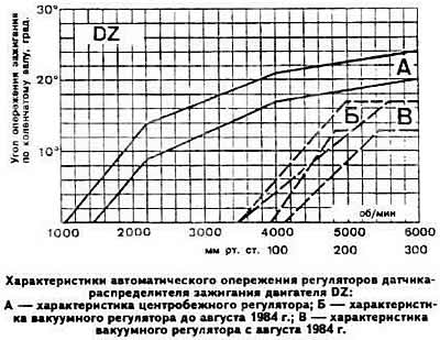
Ignition timing angle before TDC:


  • yP, YZ engines: O*1);
  • eP engine: 9°±1*2),3); 6°±1*2),4);
  • motors DS, OS: 18°±1°*1);
  • dZ engine: 6°±1°2).


1) With the hose connected to the vacuum regulator.
2) With the hose disconnected from the vacuum regulator.
3) Until July 1983.
4) Since July 1983.
4) Since July 1983.

4) Since July 1983.


4) Since July 1983.


4) Since July 1983.


4) Since July 1983.


4) Since July 1983.


4) Since July 1983.


4) Since July 1983.


4) Since July 1983.


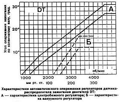
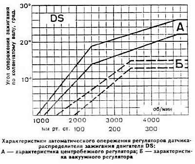
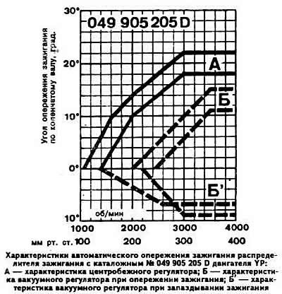
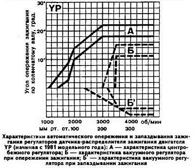
Note. When testing the ignition distributor sensor removed from the engine on a bench, divide the values indicated on the graph by two. When testing on the engine, add the initial ignition timing value.


Switch


The switch converts the control pulses of the generator sensor into current pulses in the primary winding of the ignition coil. It has a seven-plug connector (plug No.7 is a reserve). After 1.5 seconds after the ignition distributor sensor shaft stops, a special purpose of the switch smoothly breaks the ignition coil power supply circuit, preventing sparking. This prevents excessive heating of the ignition coil with a low resistance value of the primary winding.

Ignition coil


Brand and catalog number: Bosch 0 221 122 023.

Primary winding resistance at 20°C, Ohm: 0.64-0.66.

Resistance of secondary winding at 20°C, kOhm: 2.5-3.5.

High voltage wires


High voltage wires are equipped with interference suppressing tips.

Resistance of high voltage wires, kOhm:
  • central wire: 22.0±0.8;
  • other wires: 6.0±1.4.

Resistance of noise-suppressing tips, kOhm:
  • from the spark plug side: 1.0±0.4;
  • from the ignition distributor sensor side: 5.0±1.0

from the ignition distributor sensor side: 5.0±1.0
The article was checked by auto expert Georgy Rodionov
This article is available at russian, bulgarian, belarusian, ukrainian, serbian, croatian, romanian, polish, slovak, hungarian

Share information:
Previous articles
Audi 80 B2: Engine EP, YP, YZ, DT, DS, DZ
Next articles

Technical characteristics of the contact ignition system
Technical characteristics of engines with the K-Jetronic fuel…
Technical characteristics of the Pierburg 2E2 carburetor
Technical characteristics of the Keihin 26-30 DC carburetor
Tightening torques of main threaded connections, kgf.m
Checking and adjusting clearances in the valve drive mechanism
Construction of hydraulic tappets
Operating principle of hydraulic tappets


Similar articles on other Audi car models:
Ignition system — technical characteristics Audi 100 C3 (1982-1990, petrol)
Ignition System Specifications Audi A3 Type 8L (1996-2003)
Technical characteristics of the braking system Audi A4 B8 (2007-2015)
Technical characteristics of the ignition system Audi A6 C4 (1994-1997)
General information about the ignition and fuel injection system Audi A8 D2 (1994-2002)
Ignition System — Control Data Audi Q5 Type 8R (2008-2017)
Radio or Navigation System Plus — Activating Security Coding Audi A2 (1999-2005)
Link to this page in different formats


Visitor comments

No comments yet


How much will 37 + 17 =


80(B4, 1991-1996) 
  • General information
  • User manual
  • Maintenance
  • Troubleshooting
  • Power unit
  • Engine
  • Cooling system
  • Heating and ventilation
  • Petrol injection
  • Diesel fuel system
  • Fuel system
  • Exhaust systems
  • Ignition system
  • Transmission
  • Clutch
  • Car gearbox
  • Chassis
  • Brake system
  • Suspension and steering wheel
  • Body
  • Body and trim
  • Electrical equipment
  • Electrical system
  • Electrical circuits
 
80(B3, 1986-1991) 
  • General information
  • Repair characteristics
  • Maintenance
  • Power unit
  • Gasoline engine
  • Diesel engine
  • Engine lubrication system
  • Fuel system (gasoline)
  • Injection system (gasoline)
  • Fuel system (diesel)
  • Ignition system
  • Cooling system
  • Heater
  • Exhaust system
  • Transmission
  • Clutch and gearbox
  • Chassis
  • Steering
  • Brake system
  • Car suspension
  • Body
  • Body elements
  • Electrical equipment
  • Power devices
  • Lighting and appliances
  • Electrical circuits
 
80(B3, 1986-1991, petrol) 
  • General information
  • User manual
  • Maintenance
  • Power unit
  • Engine 4-cylinder
  • Engine 5-cylinder
  • Cooling system
  • Fuel and exhaust systems
  • Ignition system
  • Transmission
  • Clutch
  • Mechanical transmission
  • Automatic transmission
  • Drive shafts
  • Chassis
  • Brake system
  • Suspension
  • Steering
  • Body
  • Exterior
  • Interior
  • Electrical equipment
  • Equipment and devices
  • Electrical circuits
 
80(B2, 1979-1986) 
  • General information
  • User manual
  • Power unit
  • Engine FZ
  • Engine EP, YP, YZ, DT, DS, DZ
  • Transmission
  • Clutch
  • 4 speed gearbox
  • 5 speed gearbox
  • Front wheel drive
  • Chassis
  • Front suspension
  • Rear suspension
  • Steering
  • Brake system
  • Electrical equipment
  • Equipment and devices
  • Electrical circuits
 
AudiManual.ru © 2017-2026 · Mobile version · Feedback · Sitemap: EN BG BY UA RS HR RO PL SK HU · Site search · News and articles
80 B2 · 80 B3 petrol · 80 B3 · 80 B4 · 100 C3 diesel · 100 C3 petrol · 100 C3 · 100 C4 petrol · 100 C4 · A3 Type 8L · A4 B5 petrol · A4 B5 · A4 B6 petrol · A4 B6 · A4 B7 · A4 B8 · A6 C4 · A6 C5 · A6 C5 Allroad · A8 D2 · Q5 Type 8R · Q7 Typ 4L · Audi A2 ·
This site uses cookies 🍪. Click the button to accept this fact.