
Table of contents: General description ↓ Removal ↓
General description
1. The turbo generator is installed on models with DE, NC and 1T engines and is located on the exhaust manifold. Lubrication is provided by an oil feed pipe coming from the oil filter mounting bracket. The oil returns to the pan through a return pipe, which is connected to the cylinder block wall. The turbo generator block has a built-in relief valve and a vacuum diaphragm drive, which is used to control the boost pressure.
2. The internal components of the turbo generator rotate at very high speed and are also extremely sensitive to contamination; small particles of dirt that get into the turbine can cause major damage.
Warning: Thoroughly clean the area around all oil line couplings before disconnecting them to prevent dirt from entering the system. Store removed components in a sealed container to prevent contamination. Cover the turbo-generator air inlet ducts to prevent dirt from entering, and use only thick (lint-free) cloths for cleaning. Do not run the engine with the turbo-generator air inlet duct disconnected; when the engine speed increases, the boost may suddenly turn on, and there is a risk of foreign particles being sucked into the system.
Removal
Note: The following procedure describes how to remove the turbo generator while leaving the exhaust manifold in place, however this method requires the use of special wrenches to access the internal mounting nuts. An alternative method is to remove the manifold with the turbo generator in place and then separate the unit as described in Chapter 4.
3. Apply the handbrake, then jack up the front of the car and place it on axle stands.
4. Remove the lower skid plate from under the engine compartment.
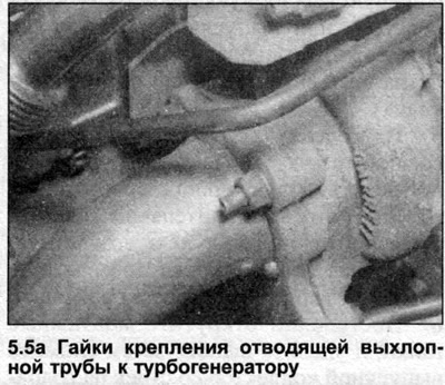
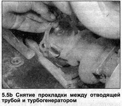
5. Remove the nuts and disconnect the exhaust outlet pipe from the exhaust manifold. Support the exhaust outlet pipe on an axle stand and remove the gasket (see illustrations).
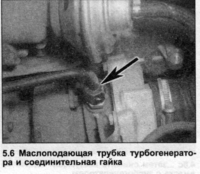
6. Unscrew the union nut and disconnect the oil supply pipe from the turbo generator (see illustration).
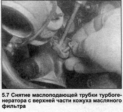
7. If necessary, remove the bolts and separate the oil feed pipe from the top of the oil filter bracket. Remove the gasket (see illustration).
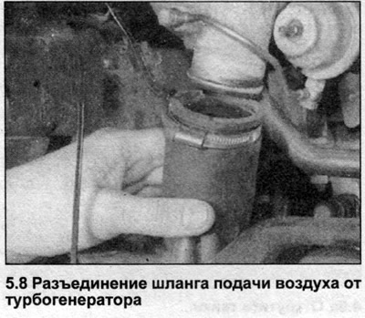
8. Loosen the clamp and disconnect the air supply hose from the turbo generator (see illustration).
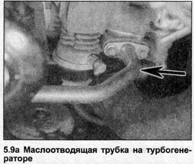
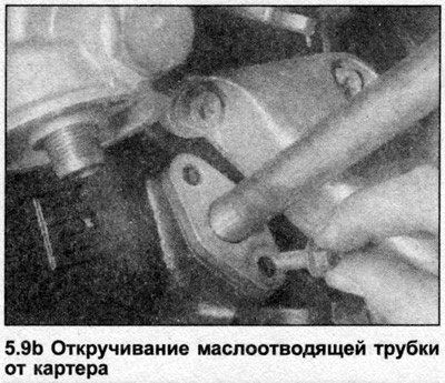
9. Unscrew the bolts and disconnect the oil drain pipe from the turbogenerator and crankcase (see illustrations). Remove gaskets or O-rings where present.
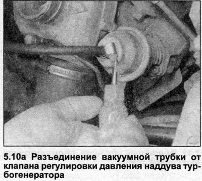
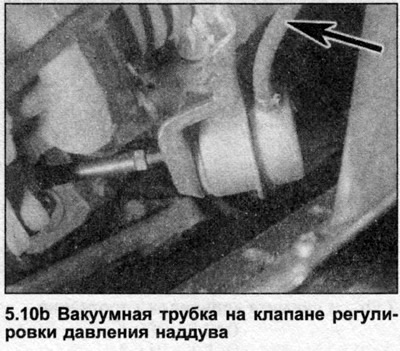
10. Disconnect the vacuum tube from the turbogenerator boost pressure control valve (see illustrations).
11. Loosen the mounting nuts and remove the turbo generator downwards from the exhaust manifold. Discard the nuts and use new ones when reassembling.
12. Clean the contact surfaces of the turbogenerator and exhaust manifold.
13. Position the turbo generator on the manifold, then apply a small amount of high-temperature grease to the threads of the through-struts. Install and gradually tighten the mounting nuts to the specified tightening torque Specifications.
14. Connect the vacuum tubes.
15. Install the oil drain pipe together with new gaskets or O-rings, and tighten the bolts to the specified tightening torque Specifications.
16. Connect the air supply hose and tighten the clamp.
17. Before installing the oil feed pipe, inject oil into the opening on the turbo generator. This is necessary to provide the turbine with lubrication during the first start.
18. Install the oil feed pipe and tighten the union nut.
19. Connect the outlet pipe to the manifold, together with a new gasket, and tighten the nuts to the specified tightening torque Specifications.
20. Install the lower skid plate, then lower the vehicle to the ground.
21. When first starting the engine, it is important to let it idle for a few minutes until the oil pressure has stabilized.
[The original article is posted on the resource «AUDIMANUAL.ru»]