
Table of contents: Mounting position of the charge air… ↓ Removal and installation a… ↓ Replacement of the turbocharger… ↓ Charge air cooling system ↓
Note: All hose connections must be secured with standard hose clamps appropriate for the model year. Hoses and hose fittings syst. air boosters must be cleaned of oils and grease before installation. Only with nipple connections sealed. the ring and sealing surface must be lightly moistened with oil. The supercharging system must be sealed. Self-locking nuts must be replaced. For installing spring band clamps, it is recommended to use special pliers "VAS 6362" or special pliers "VAG 1921". Fill oil into the turbocharger through the connecting nipple for the supply oil line. After installing the turbocharger, leave the engine running at idle speed (do not increase the speed) for 1 minute to ensure oil is supplied to the turbocharger.
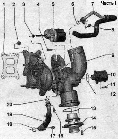
Part I
1. Gasket: replace.
2. Nut: replace; 25 Nm; lubricate the threads of the studs with high-melting grease.
3. Nut: 9 Nm.
4. Bolt: 3 Nm.
5. Boost pressure regulator "V465".
6. Sealing ring: replace.
7. Return coolant line.
8. Bolt: 9 Nm.
9. Turbocharger.
10. Turbocharger bypass valve "N249": observe installation. position.
11. Bolt: 7 Nm.
12/13. Sealing ring: replace.
14. Fitting.
15-17. Bolt: 9 Nm.
18. Sealing ring: replace.
19. Return oil line.
20. Sealing ring: replace.
Mounting position of the charge air recirculation valve "N249"
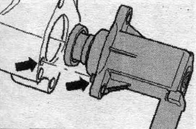
Take into account the installation. position of the "arrow".
Removal and installation a turbocharger
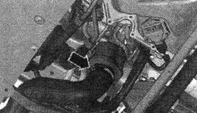
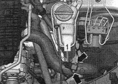
Open the expansion lid. tank. Remove the sound insulation. Disconnect the hose clamp "arrow", remove the air duct hose and set it aside.
Do not tilt the release components in the front muffler more than 10°. Loosen the bolted connections "arrows" and slide the clamping sleeve back.
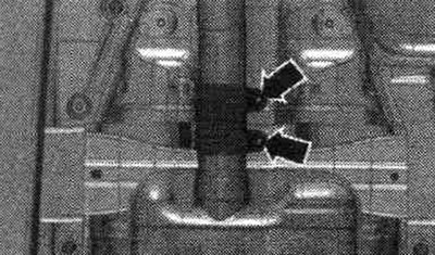
Lower the front muffler a little and tie it to the crossbar "arrow".
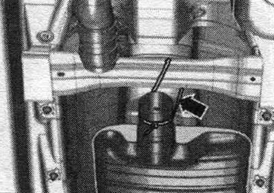
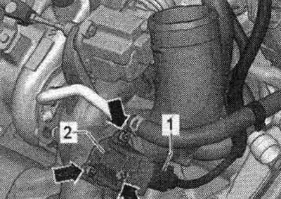
Unscrew nut "2" from below, drain the coolant.
Unscrew screw "1" and remove the return oil line. Unscrew screw "2" and turn it 2 turns.
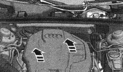
Remove the "arrow" engine cover.
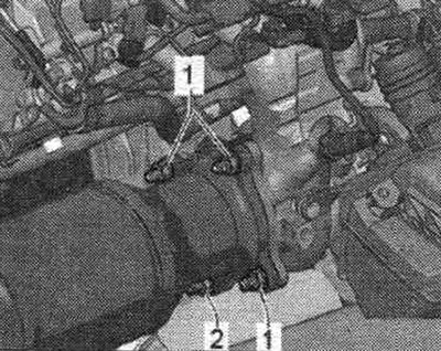
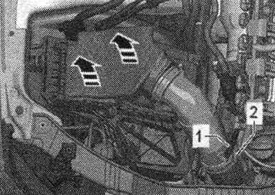
Disconnect hose "1" from the air filter. Release the air intake pipe "2". Remove the air filter housing. filter upwards with the "arrows" pointing upwards. Seal off the turbocharger using the plugs from the "VAS 6122" engine plug kit.
Disconnect connector "1" of the lambda probe "G39" and the lambda probe heater "Z19" and release the wiring.
Unscrew the crankcase ventilation hose "arrow" from the turbocharger.
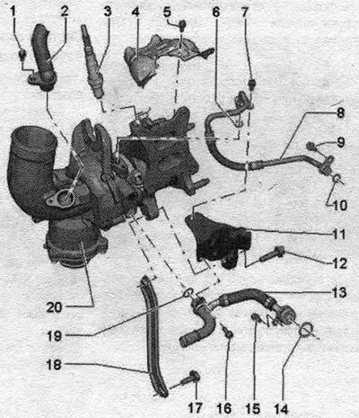
Part II
1.Screw: 9Nm.
2. Hose.
3. Lambda probe "G39" and heating element of lambda probe "Z19": the threads of new lambda probes are lubricated with mounting paste; when reusing the same lambda probe, lubricate its threads with heat-resistant paste; heat-resistant paste; do not allow mounting or refractory grease to enter the grooves of the lambda probe body.
4. Protective screen.
5. Bolt: 9 Nm.
6. Sealing ring: replace.
7. Bolt: 9 Nm.
8. Oil supply line.
9. Bolt: 9 Nm.
10. Sealing ring: replace.
11. Protective screen.
12. Bolt: 9 Nm; lubricate with refractory grease; refractory grease, see.
13. Coolant supply line.
14. Sealing ring: replace.
15...17. Screw: 9 Nm.
18. Support.
19. Sealing ring: replace.
20. Turbocharger.
Disconnect connector "1" from turbocharger bypass valve "N249".
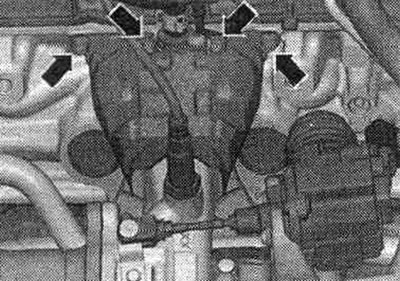
Unscrew nuts "1" from above and move the neutralizer back. Remove the heat shield "arrows".
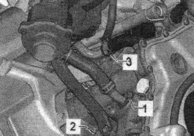
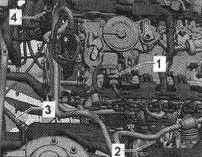
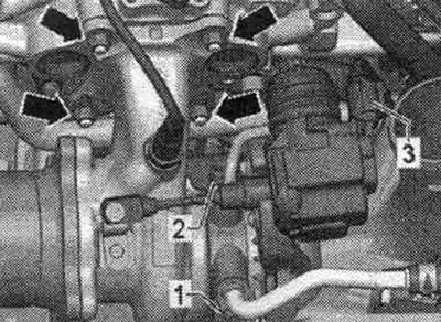
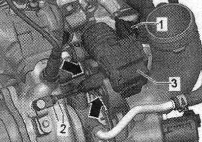
Unscrew screw "1" and disconnect the return hose of the system. cooling. Unscrew screw "2" and remove the pressure oil line. Disconnect connectors "3" from the turbocharger guide vane "V465". Unscrew the nuts "arrows".
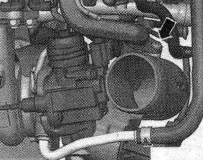
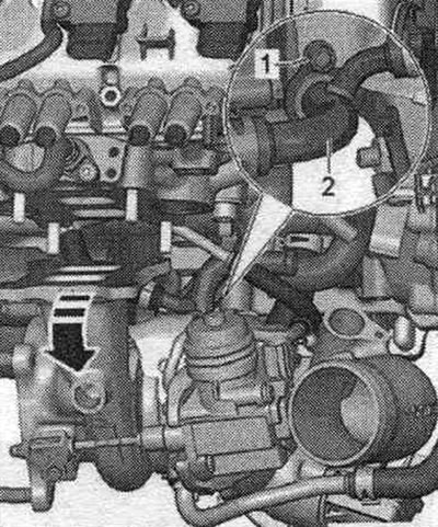
Remove the turbocharger from the studs in the direction of the arrow. With a second mechanic supporting the turbocharger, unscrew screw "1" and disconnect the pressure line of the system. cooling "2" and remove the turbocharger upwards.
Installation
Installation in reverse order. Replace the seal. gasket rings, O-rings and self-locking nuts. Lubricate the turbocharger studs with high-temperature grease; refractory grease. Fill the turbocharger with oil through the oil supply line nipple. Hoses and hose fittings syst. air boosters must be cleaned of oils and grease before installation. Secure all hose connections with hose clamps of the appropriate series. Install the neutralizer. Install the exhaust system without stress. Install air ducts with a nipple coupling. Fill with coolant. Check the oil level. After installing the turbocharger, let the engine idle (do not increase the speed) for 1 minute to ensure oil is supplied to the turbocharger.
Replacement of the turbocharger guide vane "V465"
After removal, the turbocharger guide vane "V465" must be replaced. Disconnect connectors "1" from the turbocharger guide vane "V465". Loosen locknut "2" and remove the rod from the turbocharger. Unscrew the "arrow" screws and remove the turbocharger guide vane "V465" "3".
Installation
Installation in reverse order. Adjust the new turbocharger guide vane "V465". Select item 01 - adjusting the turbocharger guide vane V4561 in the Guided Functions mode of the tester.
Charge air cooling system
Removal and installation of the charge pressure sensor "G31"
Disconnect the "1" connector of the "G31" boost pressure sensor. Loosen the "arrow" bolts and disconnect the "G31" boost pressure sensor from the air duct.
Installation
Installation in reverse order. Replace the seal. ring.
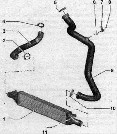
Charge air cooling system
For small indentations on the plates.
1. Intercooler.
2. Hose clamp: reinforced; 5.5 Nm.
3. Air duct hose: to turbocharger; before installation, clean from oil and grease.
4/5. Hose clamp: reinforced; 5.5 Nm.
6. Sealing ring: replace.
7. Boost pressure sensor "G31".
8. Bolt: 5 Nm.
9. Air guide tube.
10. Hose clamp: reinforced; 5.5 Nm.
11. Bolt: 7 Nm.
(This article was copied from an online resource: AudiManual)