
Component installation locations
Details A through J are not shown in the callout.
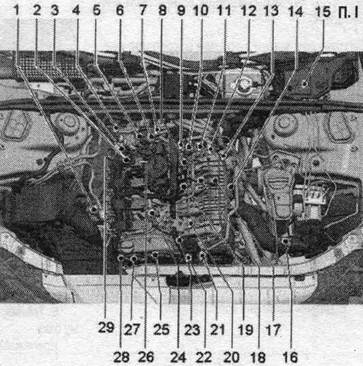
1. Lambda probe "G39" and lambda probe heating element "Z19".
2. Connector: for lambda probe "G39" and lambda probe heater "Z19".
3. Hall sensor 3 "G300": 9 Nm.
4. Lambda probe after the "G130" neutralizer and lambda probe 1 heater after the "Z29" neutralizer; connector for the lambda probe after the "G130" neutralizer and the lambda probe heater 1 after the "Z29" neutralizer.
5. Fuel pressure regulator "N276".
6. High pressure pump (HPFP).
7. Coolant temperature sensor "G62".
8. Electrical connector for MPI injectors.
9. Hall sensor "G40": 9 Nm.
10. Vacuum drive of intake flaps (intake manifold flaps).
11. Intake manifold flap valve "N316".
12. Engine speed sensor "G28": lubricate the seal. ring; replace the bolts, 4 Nm and tighten further by 45°.
13. Plug connectors for: knock sensor 1 "G61", intake manifold flap valve "N316", fuel pressure sensor "G247", intake manifold flap potentiometer "G336", Hall sensor "G40", FSI injectors N30...N33.
14. Throttle control unit "J338", throttle actuator (electric throttle control) "G186": throttle valve drive angle sensor "G187" and throttle valve drive angle sensor 2 "G188"; after each removal and installation, or after replacing the throttle control unit "J338", it is necessary to re-adapt it to the engine control unit "J623".
15. Engine control unit "J623".
16. Boost pressure sensor "G31".
17. Intake air temperature sensor "G42" with intake manifold pressure sensor "G71".
18. Knock sensor I "G61": to remove it is necessary to dismantle the coolant pump with thermostat, 20 Nm.
19. Low pressure fuel pressure sensor "G410": The low pressure fuel pressure sensor "G410" must be installed with an adapter;15 Nm.
20. Fuel pressure sensor "G247": 27 Nm.
21. Oil pressure regulating valve "N428".
22. Oil pressure sensor "F22", oil pressure drop sensor "F378" and piston cooling nozzle control valve "N522".
23. Intake manifold flap potentiometer "G336".
24. Solenoid valve 1 of the activated carbon absorber "N80".
25. Valve 1 for adjusting the timing phases "N205".
26. Ignition coils with output stages.
27. Valve 1 of the variable valve timing system for exhaust valves "N318".
28. Turbocharger bypass valve "N249" and turbocharger guide vane position sensor "V465": mounted directly on the turbocharger.
29. Actuating elements of the timing phase regulation: Actuating element 1 of the timing phase regulation "F366"; 2: "F367"; 3: "F368"; 4: "F369"; 5; "F370"; 6: "F371"; 7: "F372"; 8: "F373".
A. FSI injectors: in fuel. ramp; Injector cyl. 1 "N30". Cyl. injector. 2 "N31". Cyl. injector. 3 "N32". Cyl. injector. 4 "N33".
B. MPI injectors: in the fuel rail; Injector 2 cyl. 1 "N532". Injector 2 cyl. 2 "N533". Injector 2 cyl. 3 "N534". Injector 2 cyl. 4 "N535".
C. Fuel control unit. pump "J538".
D. Diagnostic connector: in the knee support on the driver's side.
E. Brake light switch "F" and brake pedal switch "F47": in the footwell on the brake pedal.
F. Clutch pedal position sensor "G476": only for vehicles with manual transmission.
G. Accelerator pedal position sensor "G79" and accelerator pedal position sensor 2 "G185": on the gas pedal (both sensors are placed in one housing).
H. Radiator fan control unit "J293": integrated into the radiator fan.
I. Oil pressure sensor, level 3 "F447".
J. Left solenoid valve of electro-hydraulic engine mount "N144": not installed on all vehicles (depending on the CP).
Technical data
| Engine specifications | Turbo-FSI engine |
| Idle speed is not regulated, but is set by the system. stabilization of idle speed | 640...800 rpm |
| Limiting the number of revolutions by disabling the injection nozzle | 6500 rpm |
| Fuel pressure at the high pressure pump inlet (created when necessary by an electric fuel pump in the tank) | 3.0...7 bar excess pressure |
| High fuel pressure (created by only one mechanical single-piston pump) | 25...200 bar excess pressure |
Engine control unit "J623"
In the engine compartment in the left switching unit.
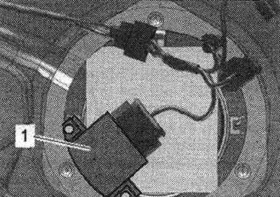
Fuel control unit. pump "J538" "1"
Accelerator pedal position sensor "G79" and accelerator pedal position sensor 2 "G185"
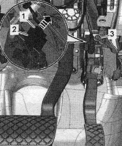
2. Plug connector.
Clutch pedal position sensor "G476" "2"
Built-in functions: clutch pedal position sensor for engine starting "F194" and clutch pedal position sensor "F36" (only in vehicles with manual transmission).
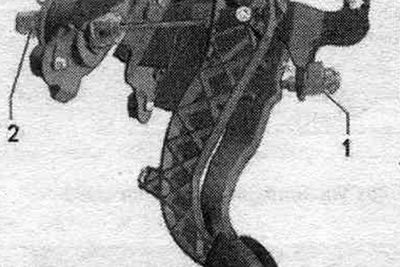
1. Brake light switch "F" and brake pedal switch "F47".
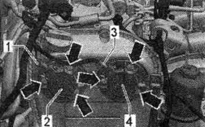
Ignition coils and actuators
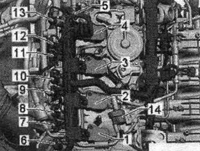
1. Coil 1 with output stage "N70"; 2. Coil 2 with output stage "N127"; 3. Coil 3 with output stage "N291"; 4. Coil 4 with output stage "N292"; 5. Hall sensor 3 "G300"; 6. Executive element 2 of the timing phase adjustment system "F367" (cyl. 1); 7. Executive element 1 of the timing phase adjustment system "F366" (cyl. 1); 8. Actuator element 3 of the timing phase adjustment system "F368" (cyl. 2); 9. Actuator element 4 of the timing phase adjustment system "F369" (cyl. 2); 10. Actuator element 6 of the timing phase adjustment system "F371" (cyl. 3); 11. Actuator element 5 of the timing phase adjustment system "F370" (cyl. 3); 12. Executive element 7 of the timing phase adjustment system "F372" (cyl. 4); 13. Actuator element 8 of the timing phase adjustment system "F373" (cyl. 4); 14. Solenoid valve 1 of the activated carbon absorber "N80".
FSI injectors
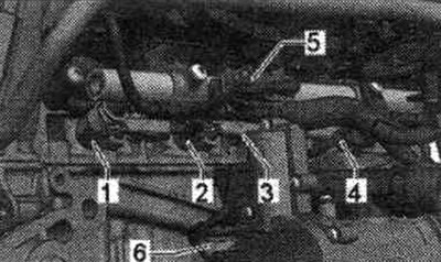
1. Injector cyl. 1 "N30"; 2. Injector cyl. 2 "N31"; 3. Cylinder injector. 3 "N32"; 4. Injector cyl. 4 "N33"; 5. Fuel pressure sensor "G247".
MPI injectors
1. Injector 2 cyl. 1 "N532"; 2. Injector 2 cyl. 2 "N533"; 3. Injector 2 cyl. 3 "N534"; 4. Injector 2 cyl. 4 "N535"; 5. Low pressure fuel pressure sensor "G410"; 6. Intake air temperature sensor "G42" with intake manifold pressure sensor "G71".
Top view
1. Low pressure fuel pressure sensor "G410"; 2. Electrical connector for MPI injectors; 3. Electrical connector for the lambda probe after the catalytic converter "G130"; 4. Hall sensor "G40"; 5. Intake air temperature sensor "G42" with intake manifold pressure sensor "G71".
Fuel pressure sensor in the high-pressure circuit
1. Fuel pressure sensor "G247".
Changing the geometry of the intake manifold
1. Vacuum drive of intake flaps (intake manifold flaps); 2. Intake manifold flap valve "N316".
Intake manifold flap potentiometer "G336" "1"
Electrical connectors
1. For FSI injectors; 2. For knock sensor 1 "G61"; 3. Oil pressure sensor, level 3 "F447"; 4. For the intake manifold flap valve "N316", fuel pressure sensor "G247", intake manifold flap potentiometer "G336", coolant temperature sensor "G62", Hall sensor "G40".
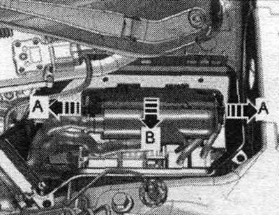
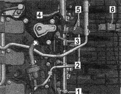
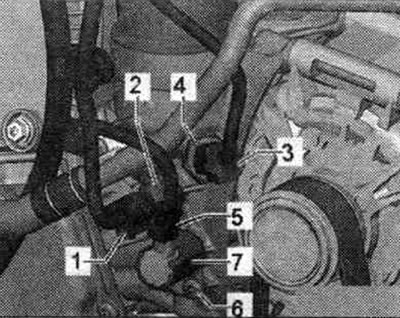
High pressure pump and Hall sensor
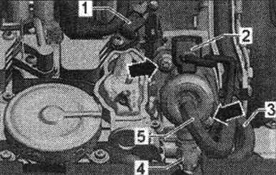
1. Hall sensor 3 "G300"; 2. Fuel pressure regulator "N276"; 3. Pressure fuel. highway to fuel. ramp with MPI injectors; 4. Pressure fuel. highway to fuel. ramp with FSI injectors; 5. Fuel supply line to the fuel tank; Arrow mounting bolts.
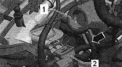
Engine speed sensor "G28" "1"
Timing phase regulator valves
1. Electrical connector of valve 1 of the exhaust valve timing control system "N318"; 2. Valve 1 of the variable valve timing system for exhaust valves "N318"; 3. Electrical connector of valve 1 of the intake valve timing system "N205"; 4. Valve 1 for adjusting the timing phases "N205".
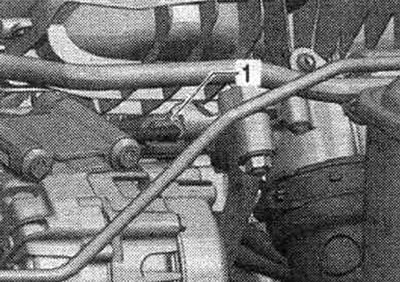
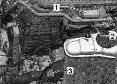
Coolant temperature sensor "G62"
1. Electrical plug connection of the coolant temperature sensor "G62"; 2. Bolt; 3. Coolant temperature sensor "G62".
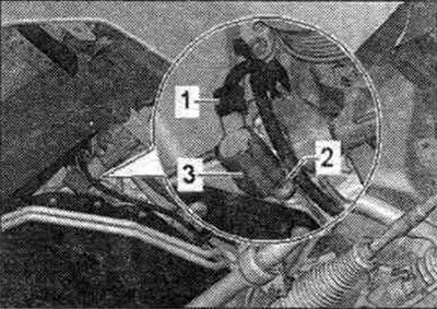
Boost pressure sensor "G31"
1. Throttle body "J338"; 2. Throttle body connector "J338"; 3. Boost pressure sensor "G31".
Oil pressure sensor
1. Electrical connector of the oil pressure sensor "F22"; 2. Oil pressure sensor "F22"; 3. Electrical connector of the low oil pressure sensor "F378"; 4. Low oil pressure sensor "F378"; 5. Electrical connector for piston cooling injector control valve "N522"; 6. Bolt; 7. Control valve for piston cooling nozzles "N522".
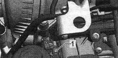
Oil pressure regulating valve "N428" "3"
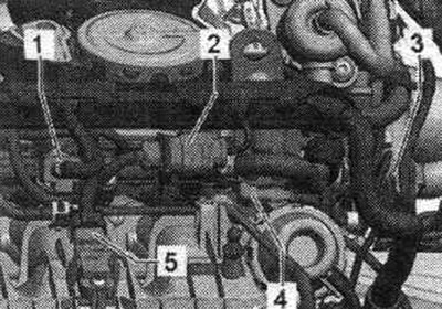
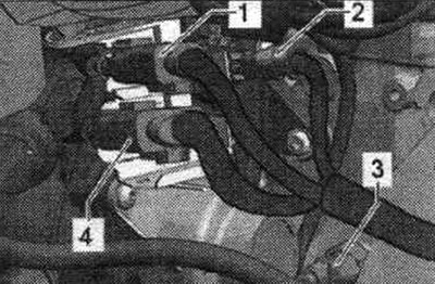
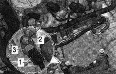
Lambda probes
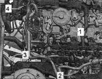
1. Electrical connector of the lambda probe "G39"; 2. Lambda probe "G39" and lambda probe heating element "Z19"; 3. Lambda probe after the "G130" neutralizer and lambda probe 1 heater after the "Z29" neutralizer; 4. Electrical connector for lambda probe after neutralizer "G130".
The original material is located on the website AUDImanual.ru