
Table of contents: Air filter ↓ Air filter ↓ Remove the air casing. filter ↓ Intake manifold ↓ Fuel rail (FSI) ↓ Fuel ramp (MPI) ↓ Removal and installation the intake… ↓ Removal and installation of fuel.… ↓ Removal and installation the… ↓ High pressure pump ↓ Removal and installation of fuel… ↓ Removal and installation MPI… ↓ Removal and installation the fuel… ↓ Removal and installation the low… ↓ Lambda probes ↓
Air filter
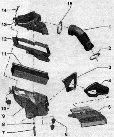
1. Air duct hose. 2. Clamp. 3. Air duct: fixed to the air duct body. filters, clean the air duct from dirt and leaves. 4. Air duct: clean the air duct from dirt and leaves. 5. Air duct: tighten the fastening to the front support panel with a torque of 2 Nm, clean the air duct from dirt and leaves. 6. Rubber bushing. 7. Drain hose: clean the branch pipe. 8. Drain hose guide. 9. Lower part of the air body. filter: clean the bottom of the air filter housing. filters from salt, dirt, leaves; check the drain for dirt and clean if necessary. 10. Fastenings of the lower part of the air housing. filter: fix; do not use lubricant! 11. Filter element: Install only the original filter element; clean the snow protection net as well (if any). 12. Air lower part nozzle. filter. 13. Upper part of the air filter housing. filter: clean the upper part of the air filter housing. filter. 14. Bolt. 15. Clamp.
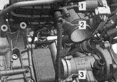
Components on a turbocharger
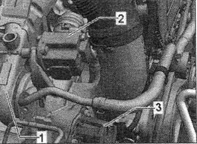
1. Turbocharger; 2. Boost pressure regulator "V465"; 3. Turbocharger air bypass valve "N249" (observe installation. position, next figure).
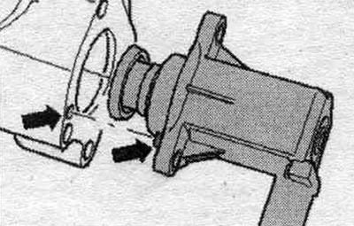
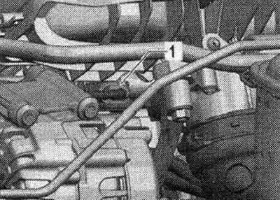
Observe the installation position of the bypass air. turbocharger valve "N249"
Air filter
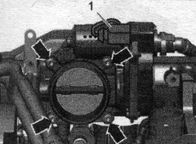
Removal the air filter element. filter
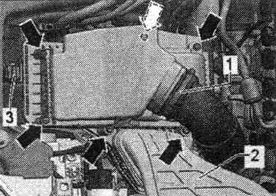
Loosen clamp "1" of the air hose leading to the turbocharger and disconnect it from the air housing. filter. Unscrew all the "arrow" screws from the top of the air filter. filter and remove it with an upward movement. Remove the old filter element.
Installation
Install only the original air filter element. filters. On the pipes and hoses of the system. there should be no oil in the boost. Do not use silicone-containing lubricants during installation. Air housing. the filter must be clean. To secure all hose connections, use clamps of the appropriate series. When blowing through the air housing. when cleaning the filter with compressed air, please note the following: in order for the air supply system to work properly, it is necessary to wipe its main components with a clean cloth. Blow out the drain at the bottom of the air with compressed air. filter. Clean the air filter housing. filter (upper and lower parts) from salt, dirt, or leaf deposits (if necessary, use a vacuum cleaner). Check the air duct from the front support panel to the air duct housing. filters for dirt and leaves. When installing the filter element, ensure that it is centered in the socket at the bottom of the air intake housing. filter. Install the upper part of the air filter housing. filter carefully, without using too much force. Install the upper part of the air duct housing. filter on the filter element without distortion (control the position of the sealing edge of the filter element). Securely fasten the air hose.
Remove the air casing. filter
Loosen clamp "1" of the air hose leading to the turbocharger and disconnect it from the air housing. filter. Remove the air duct "2", Unlock the fastening "3" of the lower part of the air. filter (press the rubber elements on the left and right and pull up). When installing, do not use lubricant in the mounting areas. Carefully remove the air duct housing. filter assembly.
Installation
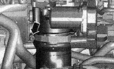
If there is a heated air supply hose (only for countries with cold climates) check the reliability of the inlet manifold "arrow" fixation (install according to the marks). Check the drain hose "1" at the bottom of the air. filters for dirt and clots (clean if necessary).
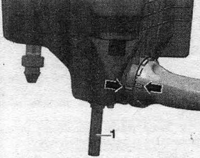
Check the air duct hose (from the side of clean air) for the absence of salt, dirt and leaf deposits. Check the inlet channel to the filter element for contamination. Install the air casing in place. filter. The water drain hose should be laid straight down without bends.
Intake manifold
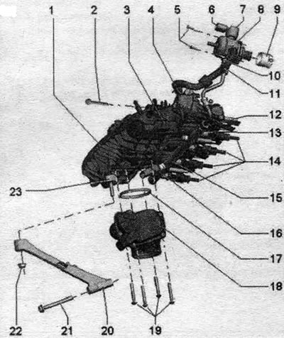
1. Intake manifold.
2. Intake manifold screw: 9 Nm.
3. Inlet throttle valve "N316".
4. Vacuum drive of intake flaps (intake manifold flaps).
5. High pressure pump screws: replace, tighten crosswise by hand and tighten to 8 Nm, then turn 90° further.
6. Electrical connector: for fuel pressure regulator "N276".
7. Fuel pressure regulator "N276".
8. High-pressure pump (HPFP): with fuel pressure regulating valve "N276"; there is an electric heater in the fuel tank. fuel pump, which supplies fuel to the mechanics. high-pressure pump; when installing the high-pressure pump, do not allow contaminants to enter the fuel system: do not hit the high-pressure pump; before installing the high pressure fuel pump. the system should not be under pressure, relieve the pressure; install fuel lines without distortions.
9. Roller plunger: After removing the high pressure pump, it can be left in the vacuum pump, removable.
10. Pressure fuel. line: to the fuel rail with FSI injectors; pressure fuel tip ball. lubricate the lines with oil; install the fuel supply line without distortions (keep it clean).
11. Pressure fuel. line: to the fuel rail with MPI injectors; install the fuel supply line without distortions (keep it clean).
12. Fuel supply line union nut: 27 Nm.
13. Fuel supply line nipple: replace, 40 Nm.
14. Injectors: replace the seal. and Teflon rings; ensure correct installation.
15. Fuel rail with FSI injectors.
16. Fuel pressure sensor "G247": 27 Nm; lubricate the threads with clean oil.
17. Sealing ring: replace.
18. Throttle valve module "J338", throttle valve drive on vehicles with electronic accelerator pedal "G186", throttle valve drive position sensor 1 on vehicles with electronic accelerator pedal "G187" and throttle valve drive position sensor 2 on vehicles with electronic accelerator pedal "G188"; after removing, installing or replacing the throttle valve unit "J338", it is necessary to re-adapt it to the engine control unit "J623" in the "Guided functions" mode using the Tester.
19. Throttle control unit bolts "J338": 7 Nm.
20. Intake manifold support.
21. Bolt: for intake manifold pipe, 20 Nm.
22. Fastening nut for intake manifold pipe: 10 Nm.
23. Rubber support: 5 Nm.
Fuel rail (FSI)
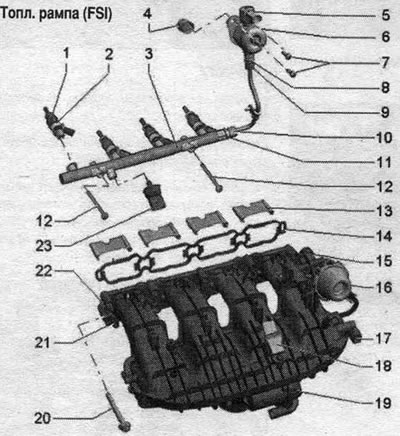
1. Injector: always replace together with the combustion chamber seal (Teflon seal. ring); replacement of seals. o-rings, ensure correct installation.
2. Support ring: replace.
3. Fuel rail for FSI injectors: tighten to 9 Nm.
4. Roller pusher.
5. Fuel pressure regulator "N276".
6. High pressure pump (HPFP): with fuel pressure regulating valve "N276"; there is an electric heater in the fuel tank. fuel pump, which supplies fuel to the mechanics. high pressure pump: when installing the high pressure pump, do not allow contaminants to enter the fuel system: before installing the high pressure fuel pump. the system should not be under pressure, relieve the pressure; install fuel lines without distortions.
7. High pressure pump bolts: replace; tighten crosswise by hand and tighten to 8 Nm, then turn 90° further.
8. Nipple for connecting the pressure line to the high-pressure pump: replace, 40 Nm.
9/10. Fuel supply line union nut: 27 Nm.
11. Nipple for connecting pressure fuel. highways to fuel. ramp: replace, 40 Nm.
12. Bolts: 9 Nm.
13. Channel dividers.
14. Gasket: check and replace if damaged.
15. Intake manifold flap regulator (intake manifold flaps).
16. Vacuum drive of intake flaps (intake manifold flaps).
17. Inlet throttle valve "N316".
18. Intake air temperature sensor "G42" with intake manifold pressure sensor "G71": 5 Nm.
19. Throttle valve module "J338", throttle valve drive on vehicles with electronic accelerator pedal "G186", throttle valve drive position sensor 1 on vehicles with electronic accelerator pedal "G187" and throttle valve drive position sensor 2 on vehicles with electronic accelerator pedal "G188"; after each removal, installation or replacement of the throttle valve unit "J338", it is necessary to re-adapt it to the engine control unit "J623" in the "Guided functions" mode using the Tester; 7 Nm.
20. Intake manifold screw: 9 Nm.
21. Intake manifold flap potentiometer "G336": After each removal, installation or replacement of the intake manifold flap potentiometer "G336", it must be re-adapted to the engine control unit "J623" in the "Guided functions" mode using the Tester.
22. Intake manifold.
23. Fuel pressure sensor "G247": 27 Nm; lubricate the threads with clean oil.
Fuel ramp (MPI)
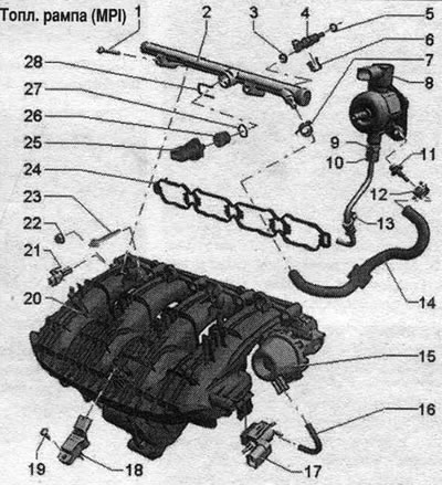
1. Bolt: for fuel rail with MPI injectors. 9 Nm.
2. Fuel rail with MPI injectors.
3. Sealing ring: replace.
4. Injector: replacing the seal. o-rings, ensure correct installation.
5. Sealing ring: replace.
6. Latches.
7. Spring clamp.
8. High-pressure pump (HPFP): with fuel pressure regulating valve "N276"; there is an electric heater in the fuel tank. fuel pump, which supplies fuel to the mechanics. high-pressure pump; when installing a high-pressure pump, do not allow contaminants to enter the fuel system; before installing the high pressure fuel pump. the system should not be under pressure, relieve the pressure; install fuel lines without distortions.
9. Fuel supply line nipple: replace, 40 Nm.
10. Union nut of fuel supply line: pressure fuel. highway to fuel. ramp with FSI injectors; pressure fuel tip ball. lubricate the lines with oil; install the fuel supply line without distortions; 27 Nm.
11. Connecting the fuel supply line. highway: 15 Nm.
12: Clamp: replace.
13. Bolt: 5 Nm.
14. Pressure fuel. main line: pressure fuel. highway to fuel. on the ramp with MPI injectors, install the fuel supply line without distortions (keep it clean).
15. Vacuum drive for intake manifold flaps.
16. Vacuum hose.
17. Intake manifold flap valve "N316".
18. Intake air temperature sensor "G42" with intake manifold pressure sensor "G71".
19. Bolt: 5 Nm.
20. Intake manifold.
21. Intake manifold flap potentiometer "G336": After each removal, installation or replacement of the intake manifold flap potentiometer "G336", it must be re-adapted to the engine control unit "J623" in the "Guided functions" mode using the Tester.
22. Nut for intake manifold: 9 Nm.
23. Intake manifold bolts: 9 Nm.
24. Gasket: check and replace if damaged.
25. Fuel pressure sensor for low pressure "G410": must be screwed on using the adapter "pos. 26"; 15 Nm.
26. Adapter: must be screwed with the low fuel pressure sensor "G410"; replace the seal. ring, 15 Nm.
27. Sealing ring: replace.
28. Clamp: for fastening the low fuel pressure sensor "G410" to the fuel rail.
Removal and installation the intake manifold
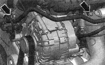
When removing or replacing the intake manifold, the intake manifold flap potentiometer "G336" must be re-adapted to the engine control unit "J623". The fuel system is under high pressure! Before opening the system. it is necessary to relieve pressure in the high-pressure circuit. Disconnect the (-) terminal from the battery. Remove the engine cover. Unscrew the "arrow" screws securing the system pipe from the intake manifold. cooling.
Open the clamp "arrow" of the air duct hose and disconnect the hose from the throttle valve module "J338" downwards.
Disconnect the following connectors.
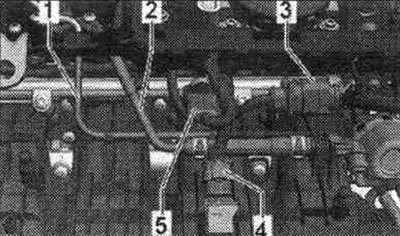
1.0t FSI injectors; 2. Knock sensor 1 "G61"; 3. Oil pressure sensor, level 3 "F447"; 4. For the intake manifold flap valve "N316", fuel pressure sensor "G247", intake manifold flap potentiometer "G336", coolant temperature sensor "G62", Hall sensor "G40".
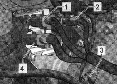
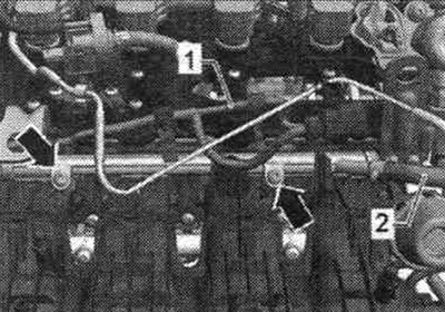
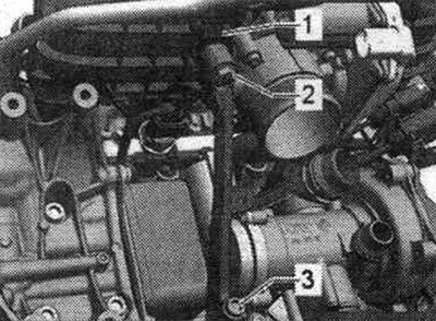
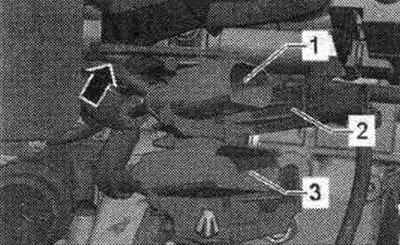
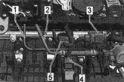
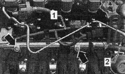
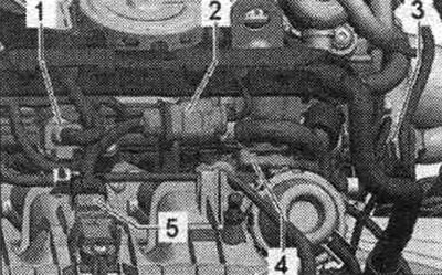
Disconnect vacuum hoses "1 and 2" from the intake manifold. Remove connector "3" from the holder. Disconnect connectors "4 and 5". Disconnect wiring harness "1" from the fuel rail. Disconnect the fuel pressure line. highway "2" from the fuel ramp.
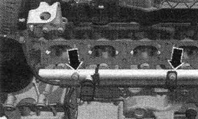
Unscrew from the fuel. ramp screws "arrows". Carefully remove the fuel upwards. ramp with nozzles. Disconnect the connector from the intake manifold flap valve "N316" "2".
Disconnect the vacuum lines "arrow" from the intake manifold flap valve "N316" "2".
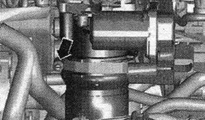
Unscrew the "arrow" fastening clamp of the high-pressure pipeline. Loosen the union nuts of the high pressure line on the high pressure pump and on the fuel line. ramp.
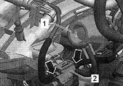
Slightly loosen the fastening nut "2" and completely unscrew the screw "3".
Disconnect connector "1" from the G336 intake manifold flap potentiometer. Remove the bolts from the intake manifold using the T10347 socket.
Move the intake manifold slightly away from the cylinder head and unscrew the connector bracket. Cover the intake ports with a clean cloth.
Installation
Screw the connector bracket into place. Install the intake manifold through the mounting pins (left and right below) onto the cylinder head. Installation is in reverse order.
Removal and installation of fuel. fSI injector ramps
The intake manifold must be removed: Removing the intake manifold. Disconnect all connectors from the injectors. Unscrew from the fuel. fuel rail screws "arrows". Remove the fuel rail from the cylinder head.
Installation
Installation in reverse order. Install the intake manifold.
Removal and installation the throttle control module "J338"
Remove the engine cover. Open the clamp "arrow" on the air duct hose and disconnect the hose downwards from the throttle valve module "J338". Disconnect the plug "1" from the throttle valve module "J338".
Loosen the 4 "arrow" bolts of the throttle module "J338" and remove the throttle module "J338".
Installation
Installation in reverse order. Clean the surface of the sealing cuff. Replace the cuff. After replacing the throttle body "J338", it must be re-adapted to the engine control unit "J623". Use the tester for this.
High pressure pump
The fuel system is under high pressure!
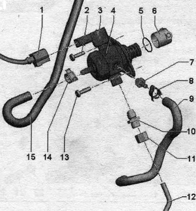
1. Electrical connector: from fuel pressure regulator "N276".
2. High pressure pump screw: replace; tighten crosswise by hand and tighten to 8 Nm, then turn 90° further.
3. Fuel pressure regulator "N276".
4. Fuel injection pump: there is an electric pump in the fuel tank. fuel pump, which supplies fuel to the mechanics. high-pressure pump; when installing a high-pressure pump, do not allow contaminants to enter the fuel system; the fuel system should not be under pressure, relieve the pressure; install fuel lines without distortions; check the seal. ring, replace if damaged.
5. Sealing ring: replace if damaged.
6. Roller tappet: In some cases, it remains in the vacuum pump after the high pressure pump is removed.
7. Connecting the fuel supply. highway: 15 Nm.
8. Clamp: replace.
9. Pressure fuel. main line: to the fuel rail with MPI injectors: install the fuel supply line without distortions (keep it clean).
10. Fuel supply line nipple: replace, 40 Nm.
11. Fuel supply line union nut: 27 Nm.
12. Pressure fuel. line: to the fuel rail with FSI injectors; pressure fuel tip ball. lubricate the lines with oil; install the fuel supply line without distortions (keep it clean).
13. High pressure pump screw: replace; tighten crosswise by hand and tighten to 8 Nm, then turn 90° further.
14. Spring clamp: replace if damaged.
15. Pressure fuel. main line: coming from the tank.
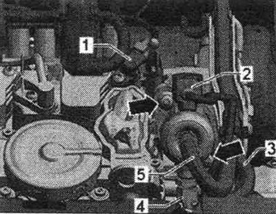
Removal and installation of fuel injection pump
Remove the high pressure pump only when the engine is cold. When installing the high-pressure pump, do not allow contaminants to enter the fuel system. Check the seal. high pressure pump ring, replace if damaged. Lubricate the high pressure fuel lines with oil and tighten them without tension. Remove the engine cover. The fuel system is under high pressure! Disconnect connector "2" from the fuel pressure regulator "N276". Disconnect fuel lines "3, 4 and 5".
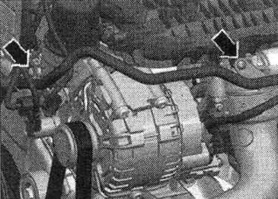
Unscrew the "arrow" clamp.
Unscrew the "arrow" screws. Carefully remove the fuel tank. high pressure pump. The roller tappet may remain in the vacuum pump.
Installation
Replace the seal. high pressure pump ring. Before installation, check the roller tappet for damage and replace if necessary. Insert the roller tappet (install a rotation stop) into the vacuum pump. To install the fuel injection pump, the roller tappet must be in the lowest position. When installing the same or a used fuel injection pump, it is necessary to replace the fuel supply connection nipple. highways (high pressure side). Turn the cardan shaft so that the roller tappet is in its lowest position. Replace the high pressure pump connection nipple. Insert the high pressure pump into the vacuum pump and tighten the bolts. Tighten the bolts by hand. Now tighten all bolts crosswise to the specified tightening torque. Install both fuels. hose and secure them with spring clamps. Tighten the fuel supply line union nut by hand. Align, relieve stress and tighten to specified torque. Reconnect connector "2" of the fuel pressure regulating valve "N276". Check the fuel tightness. syst..
Removal and installation MPI injectors
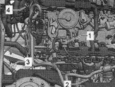
Disconnect vacuum hoses "1 and 2" from the intake manifold. Remove connector "3" from the holder. Disconnect connectors "4 and 5". Disconnect wiring harness "1" from the fuel rail. Disconnect the fuel pressure line. highway "2" from the fuel ramp.
Unscrew from the fuel. ramp screws "arrows". Carefully remove the fuel upwards. ramp with nozzles. Disconnect the connectors from the injectors.
Nozzle
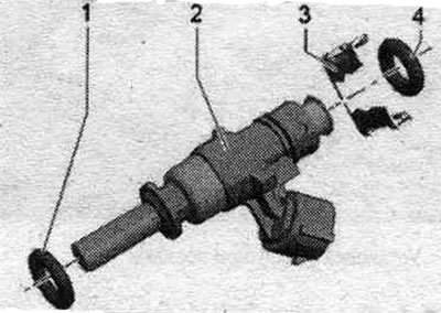
1. Replace the seal. ring (when installing, lightly lubricate with clean oil); 2. Nozzle; 3. Clamp; 4. Replace the seal. ring (when installing, lightly lubricate with clean oil).
Installation
Replace the seal. injector rings. Lubricate the seal before installation. rings with pure oil. Connect the connectors to the injectors. Press in the fuel. the ramp with the injectors by hand until it stops in the intake manifold (degrease beforehand). Installation in reverse order. Install fuel. ramp.
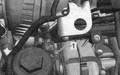
Removal and installation the fuel pressure sensor "G247"
If the fuel pressure sensor "G247" fails, the fuel pressure regulator valve "N276" is switched off, the fuel pump operates at full power and the engine operates with the available fuel pressure. As a result, engine torque drops sharply. Carefully remove the engine cover. Unscrew the "arrow" screws securing the system pipe from the intake manifold. cooling.
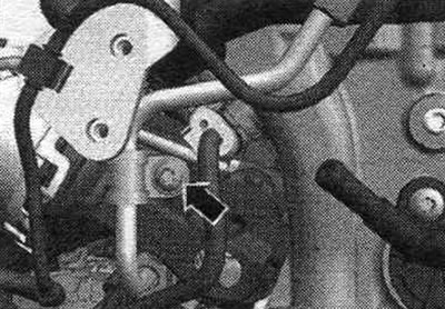
Remove the intake manifold support by unscrewing nut "2" and screw "3". Remove the rubber cushion "1" from the intake manifold.
Unlock the fuel pressure sensor connector "G247" "1" using the "T10118" installation tool. Unscrew the fuel pressure sensor "G247" "1" using the "T40218" 27 mm socket.
Installation in reverse order.
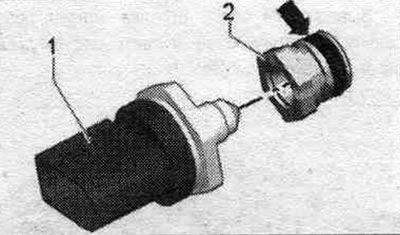
Removal and installation the low fuel pressure sensor "G410"
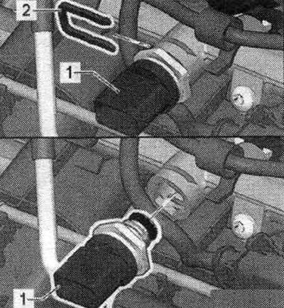
Carefully remove the engine cover. Disconnect connector "1" from the low fuel pressure sensor "G410".
Remove clamp "2", Remove low fuel pressure sensor "G410" "1" from the fuel rail.
Unscrew the low fuel pressure sensor "G410" "1" from the adapter "2".
Installation
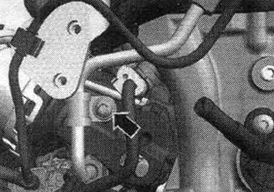
Replace the seal. ring "arrow". Screw on adapter "2" with low fuel pressure sensor "G410" "1". Carefully insert low fuel pressure sensor "G410" "1" until it stops in the fuel. rail. Secure the low fuel pressure sensor "G410" by inserting clamp "2" into the groove. Connect the connector.
Lambda probes
1. Electrical connector of the lambda probe "G39"; 2. Lambda probe "G39" and lambda probe heating element "Z19"; 3. Lambda probe after the "G130" neutralizer and lambda probe 1 heater after the "Z29" neutralizer; 4. Electrical connector for the lambda probe after the catalytic converter "G130"; Tightening torque: 55 Nm.
Note: New lambda probes are lubricated with mounting paste. Do not allow the paste to get into the grooves of the lambda probe housing. When installing used (used) for lambda probes, only the threads need to be lubricated with high-temperature paste. Avoid getting paste into the grooves of the lambda probe housing. The lambda probe wiring must be secured in the same places during installation. Avoid contact of electrical wiring with the exhaust pipe.