
Table of contents: Coolant hose connection diagram ↓ Engine temperature control actuator… ↓ Removal and installation the toothed… ↓ Removal and installation the engine… ↓ Removal and installation the coolant… ↓ Removal and installation the coolant… ↓ Removal and installation of the… ↓
Caution! Risk of burns from hot steam and hot coolant. When the engine is warm, the cooling system is under excess pressure. To relieve excess pressure, first close the expansion tank cap. tank with a rag and carefully open it. When the engine is warm, the cooling system is under pressure. If necessary, relieve pressure before performing repair work. Secure all hose connections with hose clamps of the appropriate series. To install spring clamps, it is recommended to use the hose clamp pliers "VAG 1921" or the hose clamp pliers "VAS 6340", Gaskets and seals. the rings need to be replaced. Arrows applied to the ends of the tubes and hoses of the system. cooling, must be located opposite each other.
Coolant hose connection diagram
Note: Blue = large coolant circuit. Red = small coolant circuit. Brown = heating circuit.
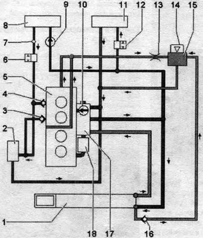
1. Radiator: change the coolant after replacement. 2. Turbocharger. 3/4. Check valve. 5. Cylinder head/block: change the coolant after replacement. 6. Coolant shut-off valve: vacuum-pressure-controlled coolant shut-off valve for Climatronic "N422". 7. Vent hole. 8. Heater heat exchanger: change the coolant after replacement. 9. Coolant circulation pump "V50": installed only in vehicles with an engine start-stop system. 10. Coolant pump. 11. Gearbox oil cooler. 12. System shut-off valve. cooling. 13. Throttle. 14. Expansion cap. tank. 15. Expansion tank. 16. Check valve. 17. Executive mechanism for regulating engine temperature "N493". 18. Oil radiator.
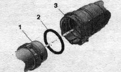
Engine temperature control actuator "N493"
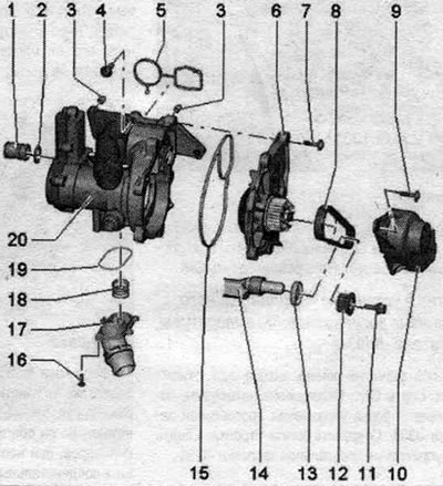
1. Connecting pipe. 2. Sealing ring: replace, moisten with coolant. 3. Centering pin. 4. Screw. 5. Gasket: replace. 6. Coolant pump: remove the protective cap from the new pump. 7. Bolt. 8. Toothed belt of the system pump. cooling. 9. Screw: 9 Nm. 10. Timing belt guard. 11. Bolt: left-hand thread; replace, 10 Nm + 90° turn. 12. Drive gear for toothed belt: install in the proper position. 13. Shaft gasket. 14. Balance shaft. 15. Gasket: replace. 16. Screw: 9 Nm. 17. Connecting pipe. 18. Spring. 19. Gasket: replace. 20. Engine temperature control mechanism "N493".
Sequential tightening
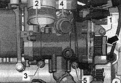
Tighten the screws in sequence. "1...5" with a torque of 9 Nm.
Sequence of tightening the bolts for fastening the system pump. cooling
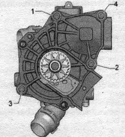
Tighten the screws securing the system pump. cooling in sequence. "1...4" with a torque of 9 Nm.
Removal and installation the toothed belt of the system pump. cooling
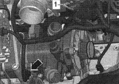
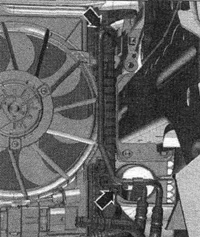
Disconnect connectors "1" from the oil pressure sensor, level 3 "F447". Unscrew the "arrow" screws and remove the timing belt cover.
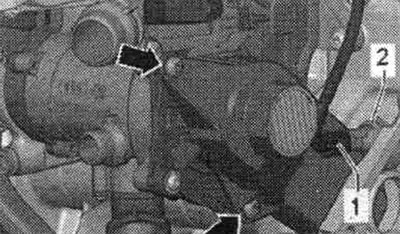
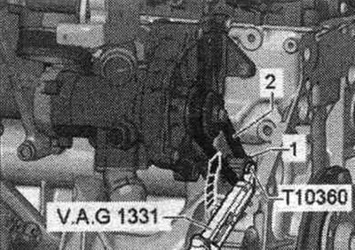
The drive pinion bolt has a left-hand thread. Unscrew bolt "1" of the system pump gear. cooling using a torque wrench and the T10360 attachment and turn it 3 turns, resting against the torsional vibration damper. Remove timing belt "2".
Installation
Installation in reverse order. Replace the drive pinion bolt. Take into account the installation. position of the toothed belt pulley. Fill with coolant.
Removal and installation the engine temperature control actuator "N493"
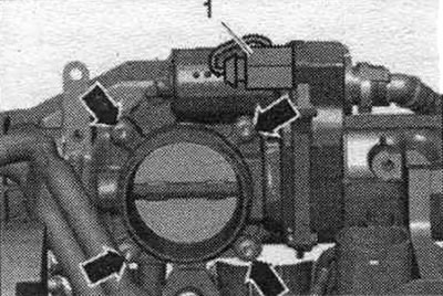
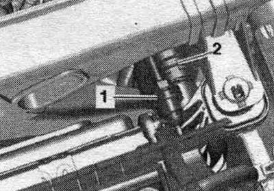
Remove the timing belt from the system pump. cooling. Drain the coolant. Disconnect plug connection "1" of the throttle control unit "J338". Unscrew the bolts "arrows" and remove the throttle control unit "J338".
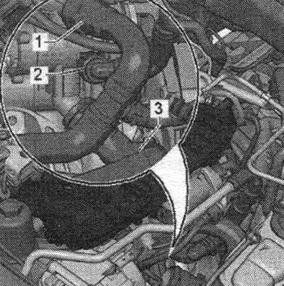
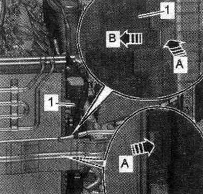
Disconnect hoses "1...3" by loosening the clamps.
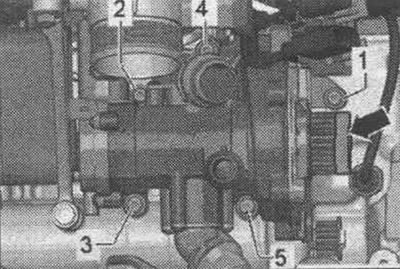
Disconnect the "arrow" connector from the engine temperature control actuator "N493". Unscrew the bracket for the cable connectors "1".
Remove bolts "1...5". Remove the engine temperature control actuator "N493" from the centering pins and disconnect it from the engine oil cooler. "Arrow" should not be taken into account.
Installation
Installation in reverse order. Replace gaskets and seals. o-rings. Wet the seal. coolant rings "4". Check that both centering pins are inserted into the cylinder block; reinsert if necessary. Insert connecting element "2" into oil cooler "1". Insert engine temperature control actuator "N493" "3" into the connecting pipe, and then install it on the centering pins of the cylinder block.
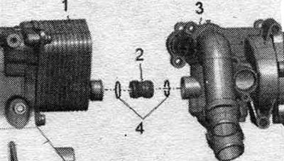
Tighten the screws securing the engine temperature control actuator "N493". When installing a new system pump. remove the protective cap "arrow" from the cooling system. Install the toothed belt of the system pump. cooling. Install the throttle control module "J338". Fill with coolant.
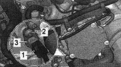
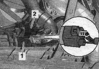
Removal and installation the coolant temperature sensor at the radiator outlet "G83"
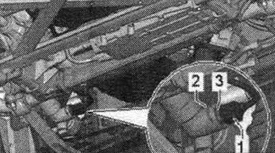
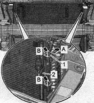
Cold engine. Remove the front sound insulation. Open the expansion tank briefly to relieve residual pressure in the cooling system. Disconnect connector "1" from radiator outlet coolant sensor "G83". Remove clamp "2" and remove radiator outlet coolant temperature sensor "G83" "3". Place a rag underneath to absorb any leaking coolant. To avoid coolant loss, it is necessary to immediately insert the coolant temperature sensor at the radiator outlet "G83" into the fitting.
Installation
Installation in reverse order. Replace the seal. rings. Check the coolant level. Install the front noise insulation shield.
Removal and installation the coolant temperature sensor "G62"
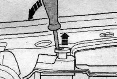
Cold engine. Open the expansion tank cover briefly. tank for relieving residual pressure in the cooling system. Disconnect plug connection "1" of the coolant temperature sensor "G62". Place a rag underneath to absorb any leaking coolant. To avoid coolant loss, immediately install the new coolant temperature sensor "G62" into the hose. Unscrew the screw "arrow" and remove the coolant temperature sensor "G62" "3".
Installation
Installation in reverse order. Replace the seal. rings. Check the coolant level.
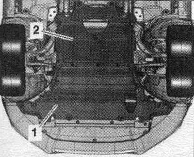
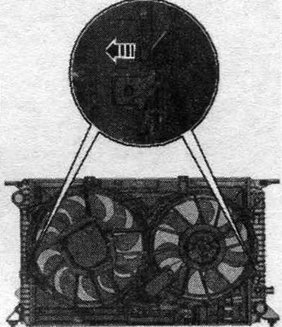
Removal and installation of the system radiator. cooling with fan frame
Radiator system. the cooling system and frame with fans can only be removed and installed as an assembly. In new designs, the condenser can no longer be removed from the radiator with the refrigerant hoses still connected. In the following description of the work, this design is referred to as "Execution 2." Remove the front noise insulation "1".
Remove amplifier "5".
Vehicles with refrigerant hoses in version 2: Remove the condenser.
Remove the panel bracket to install the headlight housing.
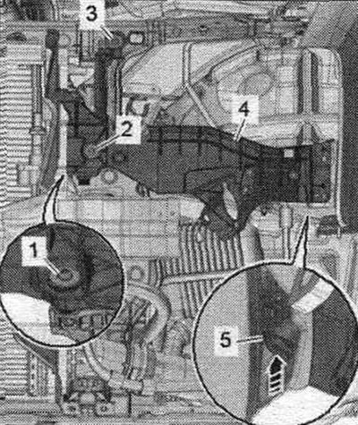
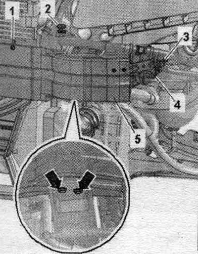
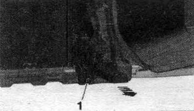
Place a service tray under the engine. Unscrew drain plug "1" and drain the coolant. Then remove the coolant hose from the radiator by loosening retaining clip "2.".
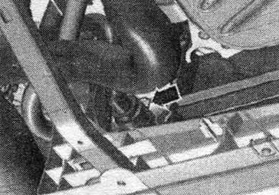
Remove the connecting nipple from the radiator by loosening the "arrow" clamp.
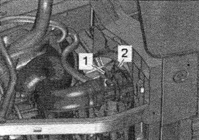
Disconnect connectors "1" and "2" from the radiator fans; to do this, move the fuse back "arrow" and press the lock down.
Vehicles with dual clutch transmission 0B5: Install a device for pumping and collecting oil under the disconnect point. Loosen the arrow bolts and disconnect the ATF lines from the radiator. To prevent ATF oil leakage, tie the ATF lines to the side member.
Close open lines and pipes with clean plugs from the VAS 6122 engine plug kit.
All models
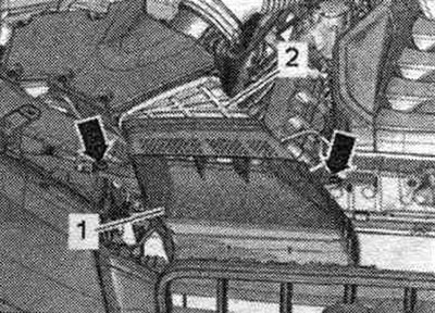
Remove the connecting nipple from the radiator by loosening clamps "1" and "2".
Unscrew the "arrow" bolts. Remove the air duct "1" from the intermediate flange "2" of the air duct housing. filter.
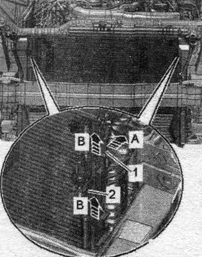
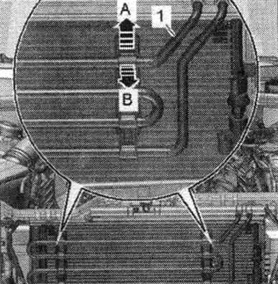
A/m with hydraulics. power steering: If equipped, unlock the fastening brackets "arrow A" and move the power steering coolant hoses "1" forward "arrow B". Remove the power steering coolant hoses from the condenser in an upward direction and place them on the engine.
All models
Unlock the fastening brackets "arrows A" and remove the air duct "1" on the left and right "arrow B".
Unlock both radiator mounting bolts on the right and left and pull them upwards "arrows".
Unscrew the bolts "1" on the left and right and remove the radiator console together with the radiator from the radiator frame "arrow". Lower the radiator slightly.
Vehicles with refrigerant hoses in version 1: The second mechanic must unlock the fastening brackets "1" "in the direction of arrow A"; the first mechanic must lift the condenser "2" upwards out of the retainers on the radiator "arrows B". Tilt the condenser with the connected coolant hoses forward.
All models
Remove the radiator. Simultaneously press the fan frame fastening tabs "arrow" on the right and left and remove the fan frame from the radiator in an upward direction.
Installation
Installation in reverse order. For small indentations on the plates. Install the air duct on the intermediate flange of the air casing. filter. Cars with DSG 0B5 gearbox: screw on the ATF lines. Connect the coolant hose using the coupling.
Install the panel bracket to the headlight housing. Install the capacitor. Install the amplifier. Fill with coolant. After replacing the radiator, the coolant should be replaced.
Cars with DSG 0B5 gearbox: check ATF level.
(The original publication in its entirety is posted on the website: AudiManual)