Repair Chevrolet Repair Toyota Repair Honda Repair AvtoVAZ Repair Mercedes-Benz Repair BMW Repair Opel
Home  |  Contacts  |  Sitemap  |    
English Русский
Български
Беларускі
Український
Српски
Hrvatski
Română
Polski
Slovenský
Magyar
AudiManual.ru


  • AUDI 80
  • AUDI 100
  • AUDI A3
  • AUDI A4
  • AUDI A6
  • AUDI A8
  • AUDI Q
  • OTHER
  • ARTICLES
D2 (1994-2002)

Removal and installation of the exhaust system (Audi A8 D2)

  • Home
  • Audi A8
  • D2 (1994-2002)
  • Power unit
  • Fuel system (diesel)
  • Removal and installation of the exhaust system
            0
The exhaust system is used to remove exhaust gases into the atmosphere, prevent them from entering the car even in minimal quantities and reduce engine noise. In order for the exhaust system to function properly, it must be in good condition. The condition of the exhaust system also affects engine power and fuel consumption.

Notes: Always replace gaskets and self-locking nuts.


After servicing and repairing the exhaust system, check that the system is installed freely, without tension, with sufficient clearance relative to the body elements.


To make it easier to subsequently unscrew the nuts and bolts that secure the system, lubricate them with Liqui Moly LM–508–ASC high-temperature paste.

Before re-installing the exhaust system components, clean the joints with sandpaper to remove any remaining sealant or rust.

The connecting element in the front exhaust pipe must not be bent more than 10°, otherwise it will be damaged.

The rear and central mufflers are made as a single unit, but each of them can be replaced separately.

Tighten the clamp mounting nuts evenly to a torque of 40 Nm.

Note: Please use a new gasket when installing.


The rear and central mufflers are made as a single unit, but each of them can be replaced separately.


Tighten the clamp fastening nuts evenly to a torque of 40 Nm.

Fig. 5.3–13. Exhaust system of vehicles with diesel engines: 1 – suspension; 2 – bracket; 3 – bolt,…

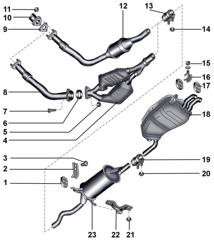
Fig. 5.3–13. Exhaust system of vehicles with diesel engines: 1 – suspension; 2 – bracket; 3 – bolt, 25 Nm; 4 – catalytic converter; 5 – nut, 25 Nm; 6 – gasket; 7 – bolt, 25 Nm; 8 – exhaust inlet pipe; 9 – gasket; 10 – exhaust manifold elbow; 11 – nut, 25 Nm; 12 – exhaust pipe with catalytic converter; 13 – front clamp; 14 – nut, 40 Nm; 15 – nut, 25 Nm; 16 – bracket; 17 – suspension; 18 – rear muffler; 19 – rear clamp; 20 – nut, 40 Nm; 21 – nut, 25 Nm; 22 – suspension; 23 – central muffler


Fig. 5.3–14. Exhaust system of vehicles with diesel engines, two catalytic converters and a…

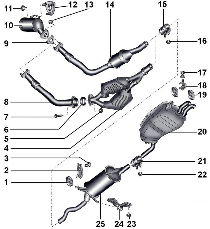
Fig. 5.3–14. Exhaust system of vehicles with diesel engines, two catalytic converters and a turbocharger: 1 – suspension; 2 – bracket; 3 – bolt, 25 Nm; 4 – catalytic converter; 5 – nut, 25 Nm; 6 – gasket; 7 – bolt, 25 Nm; 8 – exhaust inlet pipe; 9 – gasket; 10 – primary neutralizer; 11 – nut, 25 Nm; 12 – turbocharger flange; 13 – nut, 25 Nm; 14 – exhaust pipe with catalytic converter; 15 – front clamp; 16 – nut, 40 Nm; 17 – nut, 40 Nm; 18 – bracket; 19 – suspension; 20 – rear muffler; 21 – rear clamp; 22 – nut, 40 Nm; 23 – nut, 25 Nm; 24 – installation (suspension); 25 – central muffler


Fig. 5.3–14. Exhaust system of vehicles with diesel engines, two catalytic converters and a…


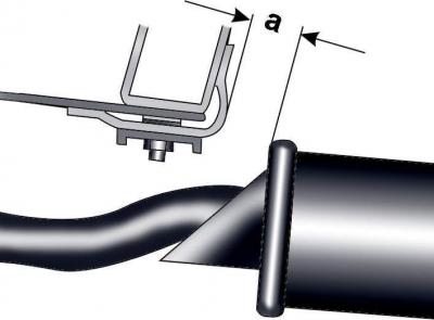
Fig. 5.3–15. Measuring the distance between the central muffler and the cross beam: a = (19±3) mm


When installing the exhaust system, the distance between the central muffler and the cross beam in a free state should be (19±3) mm (Fig. 5.3–15).


The distance between the front pipes of the central muffler and the cross beam in a free state should be 31.5 mm on front-wheel drive vehicles and 29.5 mm on all-wheel drive vehicles.

Connect the new muffler section to the old one and connect them with a clamp, positioning it so that the lower edge of its mounting bolt is located at the level of the muffler pipe.

Fig. 5.3–16. Exhaust pipe suspension elements to body elements on front-wheel drive vehicles with a…

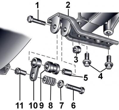
Fig. 5.3–16. Exhaust pipe suspension elements to body elements on front-wheel drive vehicles with a manual transmission: 1 – bolt, 25 Nm; 2 – bracket; 3 – self-locking nut, 25 Nm; 4 – bolts, 25 Nm; 5 – bushing; 6 – bolt, 25 Nm; 7 – plate; 8 – spring; 9 – buffer; 10 – earring; 11 – bushing


Front-wheel drive and all-wheel drive vehicles use different designs of exhaust pipe suspensions to body elements (Fig. 5.3–16, 5.3–17, 5.3–18).

Fig. 5.3–17. Exhaust pipe suspension elements to body elements on front-wheel drive vehicles with…

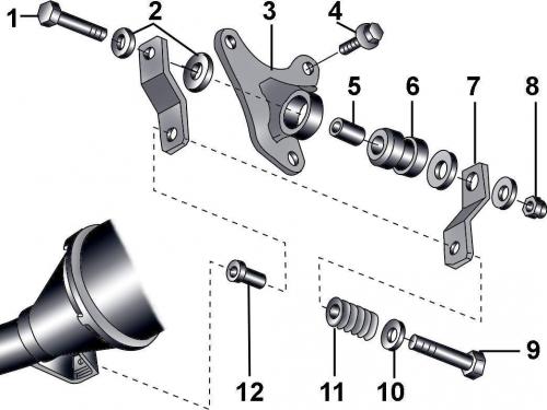
Fig. 5.3–17. Exhaust pipe suspension elements to body elements on front-wheel drive vehicles with automatic transmission: 1 – bolt, 25 Nm; 2 – washers; 3 – bracket; 4 – bolt, 25 Nm; 5 – bushing; 6 – buffer; 7 – earring, 8 – self-locking nut, 25 Nm; 9 – bolt, 25 Nm; 10 – plate; 11 – spring; 12 – bushing


Fig. 5.3–18. Exhaust pipe suspension elements to body elements on all-wheel drive vehicles with…

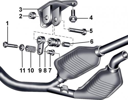
Fig. 5.3–18. Exhaust pipe suspension elements to body elements on all-wheel drive vehicles with automatic transmission: 1 – bolt, 25 Nm; 2 – self-locking nut, 25 Nm; 3 – bracket; 4 – bolt, 25 Nm; 5 – bolt, 25 Nm; 6 – bushing; 7 – bushing; 8 – buffer; 9 – earring; 10 – spring; 11 – washer


[The original article is located on the online resource AUDIMANUAL.ru]
The article was checked by auto expert Nikita Rudakov
This article is available at russian, bulgarian, belarusian, ukrainian, serbian, croatian, romanian, polish, slovak, hungarian

Share information:
Previous articles
Audi A8 D2: Fuel system (diesel)
Next articles

Device, removal and installation of turbocharger
General information about the exhaust system
Checking the pre-heating system of diesel engines
Pre-heating system for diesel engines


Similar articles on other Audi car models:
Exhaust system — removal and installation Audi 80 B3 (1986-1991, petrol)
Removal and installation of the exhaust system Audi 100 C3 (1982-1990)
Removal and installation of the exhaust system Audi A3 Type 8L (1996-2003)
Removal and installation of the exhaust system. Replacement of… Audi A4 B6 (2000-2006)
Exhaust manifold — removal and installation Audi A6 C5 Allroad (1999-2005)
Removal and installation of sensors and some lines of the engine… Audi Q7 Typ 4L (2005-2015, diesel)
Removal and installation the cooling system pump Audi A2 (1999-2005)
Link to this page in different formats


Visitor comments

No comments yet


How much will 15 + 37 =


A8(D2, 1994-2002) 
  • General information
  • User manual
  • Maintenance
  • Power unit
  • Petrol engine 2.8L
  • Petrol engine 3.7L and 4.2L
  • Diesel engine 2.5L
  • Diesel engine 3.3L
  • Ignition and injection (gasoline)
  • Fuel system (diesel)
  • Lubrication system
  • Cooling system
  • Transmission
  • Clutch
  • Car gearbox
  • Drive shafts
  • Cardan gear
  • Car suspension
  • Chassis
  • Wheels and tires
  • Steering
  • Brake system
  • Body
  • Exterior (external elements)
  • Interior (internal elements)
  • Heating and air conditioning
  • Electrical equipment
  • Fuses and relays
  • Lighting and lamps
  • Instruments and switches
 
AudiManual.ru © 2017-2026 · Mobile version · Feedback · Sitemap: EN BG BY UA RS HR RO PL SK HU · Site search · News and articles
80 B2 · 80 B3 petrol · 80 B3 · 80 B4 · 100 C3 diesel · 100 C3 petrol · 100 C3 · 100 C4 petrol · 100 C4 · A3 Type 8L · A4 B5 petrol · A4 B5 · A4 B6 petrol · A4 B6 · A4 B7 · A4 B8 · A6 C4 · A6 C5 · A6 C5 Allroad · A8 D2 · Q5 Type 8R · Q7 Typ 4L · Audi A2 ·
This site uses cookies 🍪. Click the button to accept this fact.