
Table of contents: Intake manifold ↓ Removal and installation the… ↓ Removal and installation the intake… ↓
Intake manifold
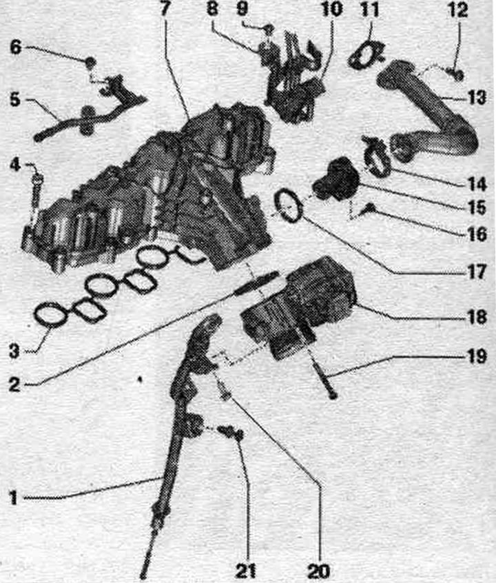
1. Guide tube: for oil dipstick.
2. Sealing cuff: replace.
3. Gasket: replace.
4. Bolt: 8 Nm.
5. Reverse fuel. highway: the image does not correspond to the version in the car.
6. Bolt; 9 Nm.
7. Intake manifold.
8-10. Not installed.
11. Gasket: replace.
12. Bolt: 20 Nm.
13. Connecting pipe: for system radiator. exhaust gas recirculation.
14. Clamp: replace; 5 Nm.
15. Nozzle: exhaust gas recirculation system.
16. Bolt: 8 Nm.
17. Sealing cuff: replace.
18. Throttle control module "J338": with throttle potentiometer "G69".
19. Bolt: 8 Nm.
20. Bolt: 9 Nm.
21. Clamp.
Removal and installation the throttle control module "J338"
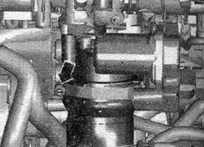
Remove the engine cover. Loosen the hose clamp "arrow" and remove the air duct hose in a downward direction.
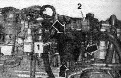
Disconnect plug connection "2". Unscrew bolt "1" of the oil dipstick guide tube. Unscrew the "arrow" bolts and remove the throttle control module "J338".
Installation in reverse order. Replace the seal. o-ring.
Removal and installation the intake manifold
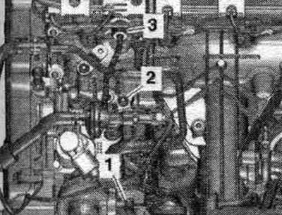
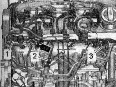
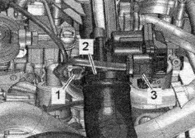
Remove the engine cover. Disconnect the glow plug connectors. Unscrew bolt "2" and union nuts "1 and 3", remove the high pressure line.
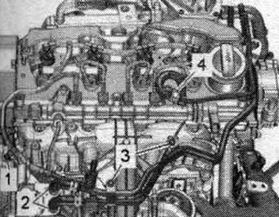
Disconnect plug connections "2 and 3". Unscrew the "arrow" bolt and push the wire holder aside. "Pos. 1" should not be taken into account. Unscrew bolts "1 and 3".
Remove the fuel hoses by loosening the hose clamps "2, 4".
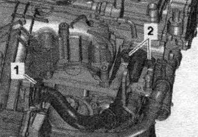
Unscrew bolt "2" and remove the differential pressure sensor "G505". Pull back the fuel. lines from the cylinder head cover up and push them to the side.
Immediately close open connections with a special cap. Open and remove clamp "1". Ignore "Pos. 2".
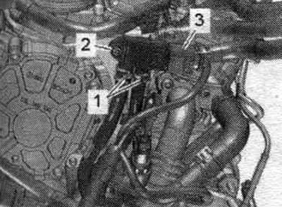
Remove the air duct hose by loosening the hose clamp "2". Unscrew the bolt "1" of the oil dipstick guide tube. Disconnect plug connection "3" of the throttle valve control unit "J338".
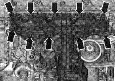
Unscrew the intake manifold "arrow" bolts from the outside to the inside crosswise using a Torx T "T10405" socket.
Installation
Installation in reverse order. Replace seals. Tighten the intake manifold bolts from the inside out in a crosswise pattern. Install the high-pressure line.
(The original article is located on the online resource «audimanual»)